The PicoScope 2000 Series: Benchtop performance, pocket size
Analog and digital inputs, plus a built-in waveform generator. Why buy lots of instruments when you can just buy one?

Entry-level price, high-end features
The PicoScope 2000 Series offers up to 100 MHz bandwidth, sampling rates up to 1 GS/s and deep memory up to 128 MS; this compact oscilloscope is incredibly capable, and yet fits on the busiest of desks with no problem.
More than just oscilloscopes, all models include a built-in function and arbitrary waveform generator. Generate pre-defined signals such as sine or square waves, with useful test and debugging features like user-defined frequency sweeps. Or use the arbitrary waveform generator to produce any signal you can draw (and you can import CSV files too!).
Mixed-signal models include a 16-channel digital input for powerful debugging. All of the PicoScope 2000 Series oscilloscopes are powered over USB to maximize portability and convenience.
A complete test and measurement lab, straight out the box

When you buy a PicoScope, it’s yours. All of it. There are no subscriptions, upgrades, hidden fees or paywalls. With regular free software updates, you’ll always have an up-to-date oscilloscope to hand. Use the wide range of serial decoders (39 and counting!), measurements,
mask tests and automation actions to power your testing and measuring.
So many low-bandwidth oscilloscopes force you to peer at a tiny, low-resolution screen. Not so with the PicoScope 2000 Series – plug in to your PC and add as many viewports as you like so you can see everything clearly.
Just getting started with PicoScope, or looking for help porting your custom PicoSDK application from Windows to Raspberry Pi? Free help from Pico’s tech support team is always available, whether you’re a beginner or an engineering pro.
Oscilloscopes that don’t compromise on quality
The PicoScope 2000 Series offers oscilloscopes with bandwidths from 10 to 100 MHz, with the 2000A models offering unbeatable value and the 2000B models offering higher bandwidth and deeper memory for advanced analysis.
PicoScopes offer unbeatable flexibility. The tools and features included with your scope are the same across the range:
• Use resolution enhancement to add up to 4 bits of vertical resolution
• Use ETS mode to increase the effective sampling rate by up to 20 times
• Use analysis tools like measurements and serial decoders, included free in PicoScope 7

Simple to use
Easy to set up, just plug in your scope and power up PicoScope 7, and you’re ready to go. Because PicoScopes use your PC’s screens, opting for a lower-bandwidth model doesn’t mean peering at a low-resolution screen with an out-of-date interface. Customize the layout so the tools you use most are always available, not hidden in menus.
For users unfamiliar with the software, help is always at hand. The software includes tooltips to explain features, plus links to in-depth articles that will guide you through your measurements, from the basics of setup to advanced features.

In-depth analysis
The PicoScope 2000 Series oscilloscopes come with up to 100 MS
MS of on-board storage. Using PicoScope 7, this can be split into up to 40 000 individual buffers (10 000 on A models). Segmented memory lets you trigger on a specific event type and capture multiple examples, without recording all the dead space in between. Most oscilloscopes in the series use advanced hardware acceleration to achieve up to 80 000 waveforms per second, indicating a quick rearm time, helping you spot that one elusive glitch.
Use Deep Measure to compare results across buffers, or use measurements to filter the captured waveforms to just those of interest, and use the waveform navigator to quickly find what you need.

Excellent dynamic performance
The PicoScope 2000 Series has noise as low as 150 μV RMS, less than −50 dB of harmonic distortion and an SFDR of more than 52 dB. Use the built-in spectrum analyzer to hunt down sources of noise, design analog filters and analyze distortion in signal chains.
The spectrum analyzer view, with its own selection of handy measurements, is ideal for demonstrating principles such as signal harmonics, interference and signal integrity.
Flexible function generator
 When you buy a PicoScope, you’re not just getting an oscilloscope. Every model in the PicoScope 2000 Series is equipped with a 12-bit function generator and arbitrary waveform generator. The intuitive interface makes it easy to generate any signal you need. Need to test the reliability of a relay? Set up a square wave, choose the frequency and duty cycle, and leave it to test overnight.
Impressive logic analyser capabilities

Accelerate your serial comms debugging with PicoScope 2000 MSO models, which have sixteen digital channels in addition to two analog channels.

Compact connectors
Your MSO comes bundled with a 20-way cable and 24 test clips
The connectors fit onto a 0.1″/2.54 mm pitch header, while the removable test clips let you quickly connect onto exposed conductors.
The lightweight design reduces mechanical
MSO groups
Group together digital channels and display them as a bus on screen – decode it into binary, hex or decimal (signed or unsigned). Or you can combine them into a single level, which is ideal for ADC and DAC testing.
Advanced triggers
Pico’s advanced trigger architecture isn’t restricted to analog channels. Trigger not just on edges, but pulse widths and even logic patterns combined across analog and digital signals.
Ideal for education

Easy to learn…
The simple UI means you can quickly get to learning the important work, without getting slowed down by deciphering the tools.
… but not limited
The PicoScope 7 software is the same across our range of real-time oscilloscopes. Learn how to use a PicoScope 2204A and you know how to operate every other Pico RTO – the high-fidelity PS4262, the ultra-fast PS6428E-D or the differential PS4444.
A complete education package
The TA560 oscilloscope training and demo board is the perfect partner. It comes packaged with complete training material to take users from the basics of setting up an oscilloscope to decoding interfaces and understanding high-frequency signals, while encouraging hands-on experimentation.
Trusted around the world
PicoScopes are used in universities around the world – from Cambridge to Xi’an.
Unmatched portability
Ultra-compact debugging
The smallest scopes in the PicoScope 2000 Series are just 14.2 × 9.2 cm (5.6 in × 3.6 in) including the BNCs. All scopes in the series are less than 2 cm (0.78 in) thick. They really do fit in your pocket.
The largest models are barely any bigger – get 1 GS/s sampling, 100 MHz bandwidth and 128 MB of waveform memory in a scope that is just 13 × 10.4 cm (5.1 x 4.1 in). Comfortably fitting on any desk, PicoScopes are the perfect choice (no matter how many projects you’ve got on the go).

Untether yourself from the mains
Every scope in the series is USB powered – no external power supply needed, just a port on your laptop. With typical power consumption less than half an amp, it won’t restrict how long you can work, even on battery power.
With the PicoScope 2000 Series, you can have your oscilloscope, logic analyzer and signal generator with you, wherever engineering takes you.
Use your PicoScope your way

Use the bundled PicoScope 7 software, create custom apps with the
powerful PicoSDK or reuse your oscilloscope for logging with PicoLog 6
Custom software development
PicoScopes offer the ultimate in flexibility. Our C-based DLLs can access every part of the hardware, unlike slow SCPI-based interfaces with a limited instruction set. Example code, for a huge range of languages and platforms, on the Pico GitHub page will get you started in no time. The PicoSDK is available on Windows and macOS, while Linux users have the option of downloading just the drivers for custom software development.
Ideal for OEM
The compact size of the PicoScope 2000 Series oscilloscopes makes them ideal for building into custom hardware. Passive cooling minimizes impact on other subsystems, and the Pico technical support team are on hand to help with any queries.
For an even more compact solution, the board-only version offers a no-frills solution with just the features you need and nothing you don’t.
For more information on OEM integration, check out the Custom Solutions hub.
Oscilloscope or logger?
Depending on your application, sometimes you don’t need a full oscilloscope – just a datalogger will do. Rather than having to buy two bits of equipment, just download the free PicoLog 6 software and connect it to your PicoScope 2000. The PicoLog API can stream data remotely for incredibly simple custom applications.
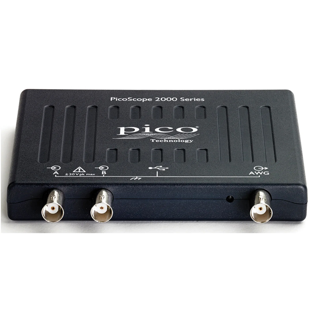
PicoScope 2000 Series inputs and outputs
Two channel models
Four channel and MSO models
Rear, all models
On the front of your PicoScope 2000 Series, you’ll find:
• Two or four input channels
• The optional 16-channel digital connector
• A function generator and arbitrary waveform generator

Spectrum analyser

The integrated FFT spectrum analyzer provides detailed frequency domain analysis, ideal for identifying noise, crosstalk and signal distortion. The spectrum analyzer in PicoScope is of the Fast Fourier Transform (FFT) type which, unlike a traditional swept spectrum analyzer, can display the spectrum of a single, non-repeating waveform. With up to a million points and comprehensive measurement tools, PicoScope’s spectrum analysis capabilities are second to none.
With a click of a button, you can display a spectrum plot of the active channels, with a maximum frequency up to the bandwidth of your scope. To focus on a specific frequency range you can directly set the start and stop values of the analyzer frequency axis.
You can display multiple spectrum views alongside oscilloscope views of the same data. A comprehensive set of automatic frequency-domain measurements can be added to the display, including THD, THD+N, SNR, SINAD and IMD. You can even use the AWG and spectrum mode together to perform swept scalar network analysis.

The spectrum works with the waveform buffer so you can capture and rewind through thousands of spectrum plots. Or, save time by using mask limit tests to scan through them all automatically. Spectrum masks and measurements also work with PicoScope actions just like in the time domain, so you can leave the spectrum running continuously and choose to save the waveform on a mask failure, or trigger an alarm when the harmonics are too high.
A full range of settings gives you control over the number of spectrum bands (FFT bins), scaling (including log/log) and display modes (instantaneous, average, or peak-hold). A selection of window functions allows you to optimize for selectivity, accuracy or dynamic range.
Scopes for a digital world
The world is getting more digital. While analog measurements remain vital in a digital environment (for tests such as signal integrity, rise time, noise and so on), often the data itself within the signal is what matters.
MSOs (Mixed Signal Oscilloscopes) are oscilloscopes with dedicated digital channels as well as the standard analog inputs. These digital channels have just one bit (logic high or low) but instead can measure many channels at once – instead of needing a four channel oscilloscope just to view one bus, an eight-channel digital input can monitor data in, data out, clocks and multiple address lines.
The digital inputs can use any of up to 40 serial decoders (with more being added all the time) as standard, and can even decode multiple different serial protocols at once.
Digital channels can also be displayed as groups with the combined total displayed in a variety of number formats or a single analog value. Advanced logic triggers will wait for a user-defined combination of levels and transitions, so you can customize it completely to your scenario.
Arbitrary Waveform Generator and Function Generator
PicoScope signal generator
Every PicoScope is equipped with a built-in function generator. Able to generate everything from simple sine and square waves, through Gaussian and PRBS waveforms, and even custom waveforms.
Frequency sweeps
The function generator can also generate frequency sweeps with controllable start and stop frequencies, dwell times and frequency steps; it is ideal for testing filter and amplifier responses.
Arbitrary Waveform Generator
The AWG allows you to output any shape waveform. Draw it by hand using the built-in editor, copy an oscilloscope trace or import data from a .csv file.
Trigger the signal generator
With PicoScope’s advanced controls, the signal generator can be triggered by any number of sources. The flexible configuration means the conditions can be an external trigger source, a mask test fail or a measurement being outside the limits.


Deep memory oscilloscopes
Pico oscilloscopes punch far above their weight in memory depth. Deep memory allows you to capture data for longer, but then zoom in and analyze the data with no loss of horizontal resolution. The zoom function lets you zoom into your waveform up to 100 million times! PicoScope 7 also allows multiple viewports to display the same signal at different zoom levels – see the details without losing sight of the bigger picture.
Deep memory combines perfectly with measurements and DeepMeasure™ so that you can analyze a huge amount of data at once, for the most accurate statistics. When viewing digital data, the deep memory allows you to record and decode longer periods of communication for more in-depth analysis.

The total memory is divided between all of the active channels, including digital channels if available. The memory can also be segmented in time, so you can set up a trigger and capture data only when it matters – skipping all the dead time in between. Using the PicoScope 7 software, you can have up to a huge 40 000 segments! Searching through that many captures would be incredibly time consuming, which is why the deep memory combines with the waveform buffer, masks, measurements and persistence modes to help you find glitches and errors quickly.
Oscilloscopes with more than 48 kS of on-board memory can also make use of rapid triggering mode, where data is not returned to the PC until all of the segments are full. Pausing communications hugely decreases the re-arm time – perfect for capturing packets of digital data in quick succession. All of the data is stored on the oscilloscope, ready to be retrieved at the end of the capture.

Pico Technology pioneered the use of digital triggers back in 1991 and they have only got more powerful since. The flexibility offered by digital triggers allows for a multitude of advanced digital trigger types – more than just edges, PicoScopes can trigger on runt pulses, different length pulses, or even logical combinations of multiple digital or analog signals. Every trigger is accurately timestamped for reference, displayed as either sample intervals or raw time.
PicoScope uses the actual digitized data to trigger. Time and amplitude errors are minimized through filtering and our digital triggers can trigger on even the smallest signals – there are no limits on slew rate. The trigger is just as accurate at full bandwidth. The trigger levels and hysteresis can be set with the highest precision and resolution.
Digital triggers really excel when it comes to advanced trigger types. PicoScope allows triggers based on signal edges (rising, falling or both) but also pulse characteristics (height, width), timing (rise/fall times, dropouts) and logic. The trigger setup can be a simple threshold, or complex windows so the scope only triggers on what you were actually wanting to see.
PicoScopes with MSOs can trigger when any or all of the 16 digital inputs match a user-defined pattern. You can specify a condition for each channel individually, or set up a pattern for all the channels together using a hex or binary value.
Logic triggers allows you to combine edges and windows on the analog inputs: for instance, trigger on the rising edge of A only if B is already high, or trigger if any channel exceeds a predefined voltage range.
Careful design for signal fidelity
PC oscilloscopes, done properly.
Pico has been making oscilloscopes for over 30 years. Rather than building down to a price, our experienced engineers will design up to a specification. Each front end is carefully crafted to reduce noise, crosstalk and distortion.
All our oscilloscopes are designed in our UK office. The lessons we learn from designing a 1 GHz oscilloscope can be applied to a 10 MHz oscilloscope – continuous improvement is at the heart of what we do.

We take pride in our oscilloscopes, which is why we publish the full specification of all our products.
The result is that when you buy a PicoScope, you can trust the waveform you see on the screen.

Custom probes in PicoScope 7
Custom probes let you correct for non-ideal characteristics in probes, sensors and transducers
Improve readability
Don’t make things more complicated than they need to be: adjust the scaling and units so that you don’t have to keep translating values in your head. With a custom probe you can see the right data at a glance.
Flexible setup
Custom probes can be used to setup a channel with just one click. Configure the coupling, voltage range and filtering to match your hardware.
Advanced lookup tables
Correct for non-linear inputs with a custom lookup table. For example, a non-linear temperature probe can be effectively calibrated so that the correct temperature is displayed on screen and converted to degrees, all in one go.
Configure once, use forever
All your custom probes are saved for reuse and can be saved as part of a .psdata file, so your settings can be shared.

Capture modes
PicoScopes can be configured in many ways so you can gather the data just how you need.
- Block capture
- Rapid trigger
- Streaming mode
In block capture mode, the PicoScope stores captured data in the internal buffer memory, before processing it and transferring it over USB. Once the data is transferred, the next block can begin capturing. The buffer memory is shared equally between each enabled channel.
Block capture mode unlocks the maximum real-time sample rates of your oscilloscope. In this mode, memory communications are half-duplex: the system is only ever reading or writing, never both.
Probes for all applications
Passive probes
Models 25 MHz and upwards come bundled with 100 MHz passive probes with switchable 1:1/10:1 divider ratios. Use them in 1:1 mode for low level signals, or in 10:1 mode to minimize the impact of probing the circuit under test or to probe signals outside the oscilloscope’s usual input range.
The 10 MHz PicoScope 2204A has optional 60 MHz probes, also with switchable gain.
With the PicoScope 2204A and 2205A models, opt not to include probes if they aren’t needed, saving you money.
MSO test leads
All MSO models include a 20-way digital input cable. Color-coded for simplicity and with four ground leads for improved signal integrity, the 25 cm leads are fitted with standard 2.54 mm pitch connectors to plug into standard headers.
For other types of connection, 12 test clips are also included. These simply plug onto the end of the test leads and let you grab onto any cables.
Standard interface = flexibility
Don’t just limit yourself to measuring voltages: Pico offers battery-powered current clamps with BNC outputs (such as the TA018 60 A AC/DC current probe), which are compatible out of the box with your PicoScope 2000 Series oscilloscope.
Create a custom probe in the PicoScope 7 software and you can automatically configure the display for the current clamp’s units, range and scale.
Pico: a solid investment
At Pico, we pride ourselves on making high-quality equipment that you can trust, for years to come. That’s why we offer an industry-leading five-year warranty on all our real-time oscilloscopes.
We also offer free support for the lifetime of all our products. Get individual help from our support team of engineers on the phone, by email or on our forum, no matter what you’re working on.
Unlike many other scope manufacturers, we don’t charge to unlock extras on your kit. Everything – all the hardware and software features, plus regular software updates – is included in the price.
Pico has been designing and building USB oscilloscopes here in the UK since 1991. Backed by over 30 years of experience and continuous innovation, Pico products can compete with any offering on the market.
PASSIVE OSCILLOSCOPE PROBES
Our ergonomically designed passive oscilloscope probes are suitable for use with all major brands of oscilloscopes as well as the PicoScope range of USB Oscilloscopes. Passive probes don’t require a power supply or batteries so are lightweight and easily portable.
| Models | |||||
| Model | Bandwidth (MHz) | Channels | Probes Included | Memory | Sample Rate |
| PIC-2204A | 10 | 2 | Yes | 8kS | 100MS/s |
| PIC-2205A | 25 | 2 | Yes | 16KS | 200MS/S |
| PIC-2206B | 50 | 2 | No | 32MS | 500MS/s |
| PIC-2207B | 70 | 2 | No | 64MS | 1GS/s |
| PIC-2208B | 100 | 2 | No | 128MS | 1gs/S |
| PIC-2405A | 24 | 4 | No | 48KS | 500MS/s |
| PIC-2406B | 50 | 4 | No | 32MS | 1GS/s |
| PIC-2407B | 70 | 4 | No | 64MS | 1GS/s |
| PIC-2408B | 100 | 4 | No | 128MS | 1GS/s |
| PIC2205A MSO | 25 | 2+MSO | No | 48kS | 500MS/S |
| PIC2206B MSO | 50 | 2+MSO | No | 32MS | 1GS/s |
| PIC-2207B MSO | 70 | 2+MSO | No | 64MS | 1GS/s |
| PIC-2208B MSO | 100 | 2+MSO | No | 128MS | 1GS/s |
Accessories
 |
Passive oscilloscope probe: 100 MHz bandwidth 1:1/10:1 switchable, BNC |
 |
Replacement spring probe tips, 5 pack |
 |
Replacement rigid probe tips, 5 pack |
 |
20-way digital input cable for MSOs |
 |
Logic test clips, pack of 10 |
 |
25 MHz 700 V differential oscilloscope probe 10:1/100:1 |
|
25 MHz 1400 V differential oscilloscope probe 20:1/200:1 |
 |
50 MHz 70 V differential oscilloscope probe 10:1 |
 |
100 MHz 700 V differential oscilloscope probe 10:1/100:1 |
 |
100 MHz 1400 V differential oscilloscope probe 100:1/1000:1 |
 |
200 MHz 20 V differential oscilloscope probe 10:1 |
 |
30 A AC/DC precision current probe, BNC connector |
 |
60 A AC/DC current probe, BNC connector |
 |
200 A / 2000 A AC/DC current probe, BNC connector |
 |
600 A AC/DC current probe, BNC connector |
 |
Terminator: feed-through, 1 GHz 50 Ω 1 W BNC (m-f) |
 |
Attenuator set: 3-6-10-20 dB, 1 GHz 50 Ω 1 W BNC (m-f) |
 |
BNC plug to 4 mm (banana) plug cable, 1.2 m |
 |
BNC to BNC cable, 1.1 m |
 |
BNC plug to BNC plug cable, insulated, 5 m |
 |
BNC plug to crocodile clips cable, 1.35 m |
 |
BNC plug to 4 mm adaptor |
 |
Large dolphin clip, 1000 V CAT III, black |
|
Large dolphin clip, 1000 V CAT III, red |
 |
Multimeter probe, 1000 V CAT II, black |
|
Multimeter probe, 1000 V CAT II, red |
 |
Small crocodile clip, black |
|
Small crocodile clip, red |
 |
Sprung hook probe 1000 V CAT III, black |
|
Sprung hook probe 1000 V CAT III, red |