Comtest

PicoScope 5000 Series

Sku: PIC-5000-S

Price: Price range: R31591,65 through R83179,50 incl Vat

High speed and high resolution. Breakthrough ADC technology switches from 8 to 16 bits in the same oscilloscope.

Product Information

Flexible Resolution USB Oscilloscope

  • FlexRes 8 to 16-bit hardware resolution
  • Up to 200 MHz analog bandwidth
  • 1 GS/s sampling at 8-bit resolution
  • 62.5 MS/s sampling at 16-bit resolution
  • Up to 512 MS capture memory
  • 16 digital channels on MSO models
  • 130 000 waveforms per second
  • Built-in arbitrary waveform generator
  • 40 serial decoding protocols as standard
  • Up to 200 MHz spectrum analyzer

Today’s electronic designs employ a wide range of signal types: analog, digital, serial (both high- and low-speed), parallel, audio, video, power distribution and so on. All need to be debugged, measured and validated to ensure that the device under test is functioning correctly and within specification.

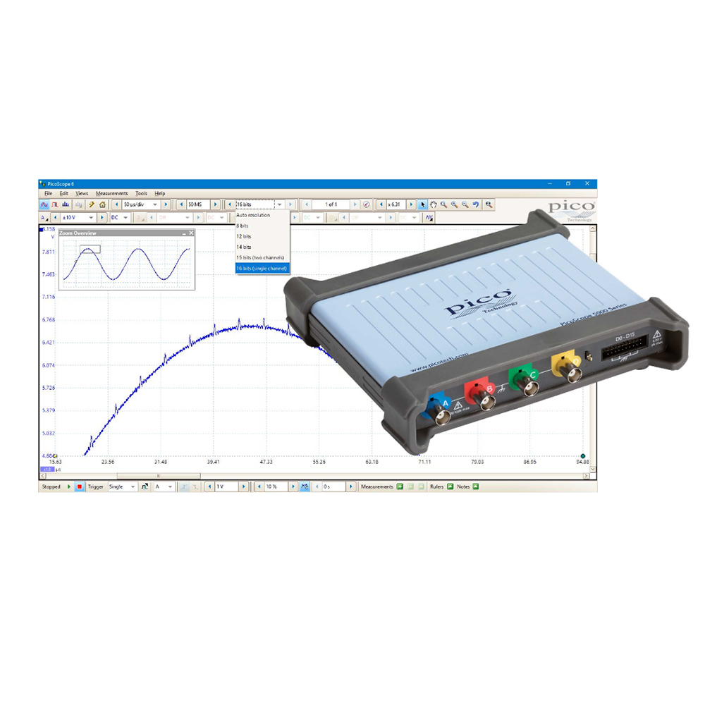
To handle this variety of signal types, PicoScope 5000D FlexRes hardware employs multiple high-resolution ADCs at the input channels in different time-interleaved and parallel combinations to optimize either the sampling rate to 1 GS/s at 8 bits, the resolution to 16 bits at 62.5 MS/s, or other combinations in between – you select the most appropriate hardware resolution for the requirements of each measurement.

2 and 4 channel models are available, all featuring a SuperSpeed USB 3.0 connection, providing lightning-fast saving of waveforms while retaining compatibility with older USB standards. The PicoSDK® software development kit supports continuous streaming to the host computer at rates up to 125 MS/s. The product is small and light, and operates silently thanks to its low-power fanless design.

Supported by the free-of-charge and regularly updated PicoScope software, the PicoScope 5000D Series offers an ideal, cost-effective package for many applications, including design, research, test, education, service and repair.

What is FlexRes?

Pico FlexRes flexible resolution oscilloscopes allow you to reconfigure the scope hardware to increase either the sampling rate or the resolution. This means you can reconfigure the hardware to be either a fast (1 GS/s) 8-bit oscilloscope for looking at digital signals, or a high-resolution 16-bit oscilloscope for audio work and other analog applications. Whether you’re capturing and decoding fast digital signals or looking for distortion in sensitive analog signals, FlexRes oscilloscopes are the answer.

Deep capture memory

PicoScope 5000D Series oscilloscopes have waveform capture memories ranging from 128 to 512 million samples – many times larger than traditional benchtop scopes. Deep memory enables the capture of long-duration waveforms at maximum sampling speed. In fact, the PicoScope 5000D Series can capture waveforms over 500 ms long with 1 ns resolution. In contrast, the same 500 ms waveform captured by an oscilloscope with a 10 megasample memory would have just 50 ns resolution.

Deep memory can be useful in other ways too: PicoScope lets you divide the capture memory into a number of segments, up to a maximum of 10 000. You can set up a trigger condition to store a separate capture in each segment, with as little as 1 µs dead time between captures. Once you have acquired the data, you can step through the memory one segment at a time until you find the event you are looking for. Powerful tools are included to allow you to manage and examine all of this data. As well as functions such as mask limit testing and color persistence mode, PicoScope software enables you to zoom into your waveform by a factor of several million. The Zoom Overview window allows you to easily control the size and location of the zoom area.

Other tools, such as DeepMeasureTM, serial decoding and hardware acceleration work with the deep memory, making the PicoScope 5000D Series among the most powerful oscilloscopes on the market.

Logic analyser / mixed signal ability

The PicoScope 5000D Series includes mixed signal models that include 16 digital inputs so that you can view digital and analog signals simultaneously.

The digital inputs can be displayed individually or in named groups with binary, decimal or hexadecimal values shown in a bus-style display. A separate logic threshold from –5 V to +5 V can be defined for each 8-bit input port. The digital trigger can be activated by any bit pattern combined with an optional transition on any input. Advanced logic triggers can be set on either the analog or digital input channels, or both to enable complex mixed-signal triggering.

The digital inputs bring extra power to the serial decoding options.  You can decode serial data on all analog and digital channels simultaneously, giving you up to 18 channels of data.  You

Arbitrary waveform and function generator

All PicoScope 5000D units have a built in 14-bit 200 MS/s arbitrary waveform generator (AWG). You can create and adapt arbitrary waveforms using the built-in editor, import them from existing oscilloscope traces, or load a waveform from a spreadsheet.

can for example decode multiple SPI, I²C, CAN bus, LIN bus and FlexRay signals all at the same time!

The AWG can also act as a function generator with a range of standard output signals, including sine, square, triangle,

DC level, white noise and PRBS. As well as the basic controls to set level, offset and frequency, more advanced controls allow you to sweep over a range of frequencies.

Combined with the spectrum peak hold option, this makes a powerful tool for testing amplifier and filter responses. Trigger tools allow you to output one or more cycles of a waveform when various conditions are met, such as the scope triggering or a mask limit test failing.


High signal integrity

Here at Pico, we’re proud of the dynamic performance of our

products. Careful front-end design and shielding reduces noise, crosstalk and harmonic distortion.

Over 25 years of high-resolution oscilloscope design experience leads to improved pulse response and bandwidth flatness.

Sensitivity at 1:1 zoom is an impressive 2 mV/div at the full resolution of the oscilloscope. If you need even more sensitivity, simply switch to high-resolution mode and zoom in. Combining 14-bit mode and zoom can provide 200 µV/div sensitivity while still providing more than 8 bits usable resolution.


High resolution for low-level signals

With resolution enhancement the PicoScope 5000D can display

low-level signals at high zoom factors.

This allows you to view and measure features such as noise and ripple superimposed on larger DC or low-frequency voltages. Additionally, you can use the Lowpass Filtering controls on each channel independently, to hide noise and reveal the underlying signal.


Software Development Kit – write your own apps

Gain & phase plot using FRA for PicoScope application

The software development kit (SDK) allows you to write your own software and includes drivers for Microsoft Windows, Apple Mac (macOS) and Linux (including

Raspberry Pi and BeagleBone).

Example code shows how to interface to third-party software packages such as Microsoft Excel, National Instruments LabVIEW and MathWorks MATLAB.

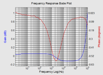
There is also an active community of PicoScope users who share code and applications on the Pico forum and PicoApps section of the picotech.com web site. The

Frequency Response Analyzer shown opposite is one of the most popular third-party applications.


Portability

The PicoScope 5000 oscilloscope is small, light and portable.

In the lab it will take up the minimum of bench space while for the engineer on the move they slip neatly into a laptop bag.

High-end features as standard

PicoScope 5000D for test of waveforms in embedded systems.

High bandwidth, high sampling rate

Despite the compact size and low cost, there is no compromise on performance, with bandwidths up to 200 MHz. This bandwidth is matched by a real-time sampling rate of 1 GS/s, allowing detailed display of high frequencies. With a real-time sampling rate of five times the input bandwidth, PicoScope 5000 Series oscilloscopes are well equipped to capture high-frequency signal detail. For repetitive signals, the maximum effective sampling rate can be boosted to 10 GS/s by using Equivalent Time Sampling (ETS) mode.

PicoScope 5000D list of serial bus decoders, with CAN bus selected.

Serial bus decoding and analysis

With its deep memory, the PicoScope 5000D Series can decode 1-Wire, ARINC 429, CAN and CAN-FD, DCC, DMX512, Ethernet 10Base-T and 100Base-TX,  FlexRay, I²C, I²S, LIN, PS/2, MODBUS, SENT, SPI, UART (RS-232 / RS-422 / RS-485) and USB 1.1 protocol data as standard.

Decoding helps you see what is happening in your design to identify programming and timing errors and check for other signal integrity issues.

Timing analysis tools help to show the performance of each design element, identifying parts of the design that need to be improved to optimize overall system performance.

CAN bus waveform decoded on a PicoScope 5000D in-graph

Graph format shows the decoded data (in hex, binary, decimal or ASCII) in a timing diagram format, beneath the waveform on a common time axis, with error frames marked in red. You can zoom in on these frames to investigate noise or distortion, and each packet field is assigned a different color, so the data is easy to read.

CAN bus waveform decoded on a PicoScope 5000D in-table

Table format shows a list of the decoded frames, including the data and all flags and identifiers. You can set up filtering conditions to display only the frames you are interested in or search for frames with specified properties. The statistics option reveals more detail about the physical layer such as frame times and voltage levels. PicoScope can also import a spreadsheet to decode the data into user-defined text strings.

Long waveform with measurements made using PicoScope DeepMeasure tool

DeepMeasure

One waveform, millions of measurements

Measurement of waveform pulses and cycles is key to verification of the performance of electrical and electronic devices.

DeepMeasure delivers automatic measurements of important waveform parameters on up to a million waveform cycles with each triggered acquisition. Results can be easily sorted, analyzed and correlated with the waveform display.

PicoScope 5000D buffer navigator showing buffer number 36 out of a total of 10 000 captured buffers.

Waveform buffer and navigator

Ever spotted a glitch on a waveform, but by the time you’ve stopped the scope it has gone? With PicoScope you no longer need to worry about missing glitches or other transient events. PicoScope can store the last ten thousand oscilloscope waveforms  or spectrum plots in its circular waveform buffer.

The buffer navigator provides an efficient way of navigating and searching through captured waveforms, effectively letting you turn back time.

PicoScope 5000D mask setup with X and Y axis tolerances.

Mask limit testing

Mask limit testing allows you to compare live signals against known good signals, and is designed for production and debugging environments.

PicoScope 5000D mask limit test with 1000 waveforms 100% passed.

Simply capture a known good signal, draw a mask around it, and then attach the system under test. PicoScope will check for mask violations and perform pass/fail testing, capture intermittent glitches, and can show a failure count and other statistics in the Measurements window.

Mask limit test on PicoScope, showing a single failed waveform out of 1000 using the Buffer Navigator.

Use the Buffer navigator to find waveforms that violate the mask.

In this case 10 000 waveforms have been captured in the buffer. Just one of those waveforms, which violated the mask, is easily found by selecting “Mask fails on Channel A” in the navigator.

Menu of trigger types available in a PicoScope 5000D MSO.

Advanced digital triggering

The majority of digital oscilloscopes still use an analog trigger architecture based on comparators. This causes time and amplitude errors that cannot always be calibrated out and often limits the trigger sensitivity at high bandwidths.

In 1991 Pico pioneered the use of fully digital triggering using the actual digitized data. This technique reduces trigger errors and allows our oscilloscopes to trigger on the smallest signals, even at the full bandwidth. Trigger levels and hysteresis can be set with high precision and resolution.

The sub-1 µs rearm delay provided by digital triggering, together with segmented memory, allows up to 10 000 waveforms to be captured in a 10 ms burst.

Setup menu of a PicoScope 5000D MSO pulse width trigger setup screen.

The PicoScope 5000 Series offers an industry-leading set of advanced triggers including pulse width, runt pulse, windowed, logic and dropout.

PicoScope 5000D MSO logic trigger with Boolean operators.

On PicoScope 5000D MSO models the digital channels can be used to form a logic trigger with Boolean operators.

PicoScope 5000D FFT spectrum analyser with options menu open

FFT spectrum analyser

The spectrum view plots amplitude against frequency and is ideal for finding noise, crosstalk or distortion in signals. The spectrum analyzer in PicoScope is of the Fast Fourier Transform (FFT) type which, unlike a traditional swept spectrum analyzer, can display the spectrum of a single, non-repeating waveform.

A full range of settings gives you control over the number of spectrum bands (FFT bins), window types, scaling (including log/log) and display modes (instantaneous, average, or peak-hold).

PicoScope 5000D spectrum view with automated measurements and on-screen rulers

You can display multiple spectrum views alongside oscilloscope views of the same data. A comprehensive set of automatic frequency-domain measurements can be added to the display, including THD, THD+N, SNR, SINAD and IMD. A mask limit test can be applied to a spectrum and you can even use the AWG and spectrum mode together to perform swept scalar network analysis.

Model PicoScope
Bandwidth (–3 dB) 60 MHz 100 MHz 200 MHz
2 channel 5242D 5242D MSO 5243D 5243D MSO 5244D 5244D MSO
4 channel 5442D 5442D MSO 5443D 5443D MSO 5444D 5444D MSO
Oscilloscope – vertical
Input type Single-ended, BNC connector
Bandwidth (–3 dB) 60 MHz 100 MHz[1] 200 MHz[1]
Rise time (calculated) 5.8 ns 3.5 ns[1] 1.75 ns[1]
Bandwidth limiter 20 MHz, selectable
Vertical resolution[2] 8, 12, 14, 15 or 16 bits
LSB size[2] (quantization step size) 8 bit mode: < 0.6% of input range
12 bit mode: < 0.04% of input range
14 bit mode: < 0.01% of input range
15 bit mode: < 0.005% of input range
16 bit mode: < 0.0025% of input range
Enhanced vertical resolution Hardware resolution + 4 bits
Input ranges ±10 mV to ±20 V full scale, in 11 ranges
Input sensitivity 2 mV/div to 4 V/div (10 vertical divisions)
Input coupling AC / DC
Input characteristics 1 MΩ ± 1% || 14 ±1 pF
Gain accuracy 12 to 16 bit modes: ±0.5% of signal ±1 LSB[3]
8 bit mode: ±2% of signal ±1 LSB[3]
Offset accuracy ±500 µV ±1% of full scale[3]
Offset accuracy can be improved by using the “zero offset” function in PicoScope software.
Analog offset range (vertical position adjust) ±250 mV (10, 20, 50, 100, 200 mV ranges),
±2.5 V (500 mV, 1 V, 2 V ranges),
±20 V (5, 10, 20 V ranges)
Analog offset control accuracy ±0.5% of offset setting, additional to basic DC offset accuracy
Overvoltage protection ±100 V (DC + AC peak)

[1] In 16-bit mode, bandwidth reduced to 60 MHz and rise time increased to 5.8 ns.
[2] On ±20 mV range, in 14 to 16-bit modes, hardware resolution reduced by 1 bit. On ±10 mV range, hardware resolution reduced by 1 bit in 12-bit mode, 2 bits in 14 to 16-bit modes.
[3] Between 15 and 30 °C after 1 hour warm-up.

Vertical (digital channels) – D MSO models only
Input channels 16 channels (2 ports of 8 channels each)
Input connector 2.54 mm pitch, 10 x 2 way connector
Maximum input frequency 100 MHz (200 Mbit/s)
Minimum detectable pulse width 5 ns
Input impedance 200 kΩ ±2% || 8 pF ±2 pF
Input dynamic range ±20 V
Threshold range ±5 V
Threshold grouping Two independent threshold controls. Port 0: D0 to D7, Port 1: D8 to D15
Threshold selection TTL, CMOS, ECL, PECL, user-defined
Threshold accuracy < ±350 mV including hysteresis
Threshold hysteresis < ±250 mV
Minimum input voltage swing 500 mV peak to peak
Channel-to-channel skew 2 ns, typical
Minimum input slew rate 10 V/µs
Overvoltage protection ±50 V (DC + AC peak)
Horizontal
Max. sampling rate
Any 1 channel
Any 2 channels
Any 3 or 4 channels
More than 4 channels
8-bit mode
1 GS/s
500 MS/s
250 MS/s
125 MS/s
12-bit mode
500 MS/s
250 MS/s
125 MS/s
62.5 MS/s
14-bit mode
125 MS/s
125 MS/s
125 MS/s
62.5 MS/s
15-bit mode[4]
125 MS/s
125 MS/s
16-bit mode[4]
62.5 MS/s

“Channel” means any analog channel or 8-bit digital port
[4]Any number of 8-bit digital ports can be used in 15-bit and 16-bit modes without affecting the maximum sampling rate

Maximum equivalent sampling rate (repetitive signals; 8-bit mode only, ETS mode) 2.5 GS/s 5 GS/s 10 GS/s
Maximum sampling rate (continuous USB streaming into PC memory)[5] USB 3, using PicoScope software: 15 to 20 MS/s
USB 3, using PicoSDK: 125 MS/s (8-bit) or 62.5 MS/s (12 to 16 bit modes)
USB 2, using PicoScope software: 8 to 10 MS/s
USB 2, using PicoSDK: ~30 MS/s (8-bit) or ~15 MS/s (12 to 16 bit modes)
Timebase ranges (real time) 1 ns/div to 5000 s/div in 39 ranges
Fastest timebase (ETS) 500 ps/div 200 ps/div 100 ps/div
Buffer memory[6] (8-bit mode) 128 MS 256 MS 512 MS
Buffer memory[6] (≥ 12-bit mode) 64 MS 128 MS 256 MS
Buffer memory[7] (continuous streaming) 100 MS in PicoScope software
Waveform buffer (no. of segments) 40 000 in PicoScope software
Waveform buffer (no. of segments) when using PicoSDK (8 bit mode) 250 000 500 000 1 000 000
Waveform buffer (no. of segments) when using PicoSDK (12 to 16 bit modes) 125 000 250 000 500 000
Initial timebase accuracy ±50 ppm (0.005%) ±2 ppm (0.0002%) ±2 ppm (0.0002%)
Timebase drift ±5 ppm/year ±1 ppm/year ±1 ppm/year
Sample jitter 3 ps RMS, typical
ADC sampling Simultaneous on all enabled channels

[5]Shared between enabled channels, PC dependent, available sample rates vary by resolution.
[6]Shared between enabled channels.
[7]Driver buffering up to available PC memory when using PicoSDK. No limit on duration of capture.

Dynamic performance (typical; analog channels)
Crosstalk Better than 400:1 up to full bandwidth (equal voltage ranges)
Harmonic distortion 8-bit mode: −60 dB at 100 kHz full scale input.
12-bit mode or higher: −70 dB at 100 kHz full scale input
SFDR 8 to 12-bit modes: 60 dB at 100 kHz full scale input.
14 to 16-bit modes: 70 dB at 100 kHz full scale input.
Noise (on most sensitive range) 8-bit mode: 120 μV RMS
12-bit mode: 110 μV RMS
14-bit mode: 100 μV RMS
15-bit mode: 85 μV RMS
16-bit mode: 70 μV RMS
Bandwidth flatness (+0.3 dB, –3 dB) from DC to full bandwidth
Triggering (main specifications)
Source Analog channels, plus: MSO models: Digital D0 to D15. Other models: Ext trigger.
Trigger modes None, auto, repeat, single, rapid (segmented memory).
Advanced trigger types (analog channels) Edge, window, pulse width, window pulse width, dropout, window dropout, interval, runt, logic.
Trigger types (analog channels, ETS) Rising or falling edge ETS trigger available on ChA only, 8-bit mode only.
Trigger sensitivity (analog channels) Digital triggering provides 1 LSB accuracy up to full bandwidth of scope.
Trigger sensitivity (analog channels, ETS) At full bandwidth: typical 10 mV peak to peak
Trigger types (digital inputs) MSO models only: Edge, pulse width, dropout, interval, logic, pattern, mixed signal.
Maximum pre-trigger capture Up to 100% of capture size.
Maximum post-trigger delay Zero to 4 billion samples, settable in 1 sample steps (delay range on fastest timebase of 0 – 4 s in 1 ns steps)
Trigger rearm time 8-bit mode, typical: 1 μs on fastest timebase
8 to 12 bit modes: < 2 μs max on fastest timebase
14 to 16 bit modes: < 3 μs max on fastest timebase
Maximum trigger rate 10 000 waveforms in a 10 ms burst, 8-bit mode
External trigger input – not MSO models
Connector type Front panel BNC
Trigger types Edge, pulse width, dropout, interval, logic
Input characteristics 1 MΩ ± 1% || 14 pF ±1.5 pF
Bandwidth 60 MHz 100 MHz 200 MHz
Threshold range ±5 V
Threshold range ±5 V, DC coupled
External trigger threshold accuracy ±1% of full scale
External trigger sensitivity 200 mV peak to peak
Coupling DC
Overvoltage protection ±100 V (DC + AC peak)
Function generator
Standard output signals Sine, square, triangle, DC voltage, ramp up, ramp down, sinc, Gaussian, half-sine
Pseudorandom output signals White noise, selectable amplitude and offset within output voltage range.
Pseudorandom binary sequence (PRBS), selectable high and low levels within output voltage range, selectable bit rate up to 20 Mb/s
Standard signal frequency 0.025 Hz to 20 MHz
Sweep modes Up, down, dual with selectable start / stop frequencies and increments
Triggering Can trigger a counted number of waveform cycles or frequency sweeps (from 1 to 1 billion) from the scope trigger, external trigger or from software. Can also use the external trigger to gate the signal generator output.
Output frequency accuracy Oscilloscope timebase accuracy ± output frequency resolution
Output frequency resolution < 0.025 Hz
Output voltage range ±2 V
Output voltage adjustments Signal amplitude and offset adjustable in approx 0.25 mV steps within overall ±2 V range
Amplitude flatness < 1.5 dB to 20 MHz, typical
DC accuracy ±1% of full scale
SFDR > 70 dB, 10 kHz full scale sine wave
Output resistance 50 Ω ±1%
Connector type BNC(f)
Overvoltage protection ±20 V
Arbitrary waveform generator
AWG update rate 200 MHz
AWG buffer size 32 kS
AWG resolution 14 bits (output step size approximately 0.25 mV)
AWG bandwidth > 20 MHz
AWG rise time (10% to 90%) < 10 ns (50 Ω load)

Additional AWG specifications including sweep modes, triggering, frequency accuracy and resolution, voltage range, DC accuracy and output characteristics are as the function generator

Probe compensation pin
Output characteristics 600 Ω
Output frequency 1 kHz
Output level 3 V peak to peak, typical
Overvoltage protection 10 V
Spectrum analyser
Frequency range DC to 60 MHz DC to 100 MHz DC to 200 MHz
Display modes Magnitude, average, peak hold
Y axis Logarithmic (dbV, dBu, dBm, arbitrary dB) or linear (volts)
X axis Linear or logarithmic
Windowing functions Rectangular, Gaussian, triangular, Blackman, Blackman–Harris, Hamming, Hann, flat-top
Number of FFT points Selectable from 128 to 1 million in powers of 2
Math channels
Functions −x, x+y, x−y, x*y, x/y, x^y, sqrt, exp, ln, log, abs, norm, sign, ceiling, floor, top, base, amplitude, derivative, integral, rise time, fall time, RMS, RMS ripple, phase, delay, deskew, true power, apparent power, reactive power, power factor, DC power, crest factor, area AC, positive area at AC, negative area at AC, absolute area at AC, area at DC, positive area at DC, negative area at DC, absolute area at DC, sin, cos, tan, arcsin, arccos, arctan, sinh, cosh, tanh
Filter functions Low pass, high pass, band stop, band pass
Graphing functions Frequency, duty cycle (positive and negative)
Buffered functions Min, max, average, peak
Operands A, B, C, D (input channels), T (time), reference waveforms, pi, D0−D15 (digital channels), constants
Automatic measurements
Scope mode Amplitude measurements: Minimum, maximum, base, top, negative overshoot, positive overshoot, peak to peak, amplitude, mean, RMS, RMS ripple
Time measurements: Frequency, cycle time, negative duty cycle, positive duty cycle, edge count (rising, falling, either) high pulse width, low pulse width, rise time, fall time, rising rate, falling rate
Multi-channel measurements: Phase, delay
Power measurements: True power, apparent power, reactive power, power factor, DC power, crest factor, area at AC, positive area at AC, negative area at AC, absolute area at AC, area at DC, positive area at DC, negative area at DC, absolute area at DC
Spectrum mode Frequency at peak, amplitude at peak, total power, THD %, THD dB, THD+N, SFDR, SINAD, SNR, IMD
Statistics Minimum, maximum, average, standard deviation
DeepMeasure™
Parameters Cycle number, cycle time, frequency, low pulse width, high pulse width, duty cycle (high), duty cycle (low), rise time, fall time, undershoot, overshoot, max. voltage, min. voltage, voltage peak to peak, start time, end time
Serial decoding
Protocols 1-Wire, 10BASE-T1S, ARINC 429, BroadR-Reach, CAN, CAN FD, CAN J1939, CAN XL, DALI, DCC, DMX512, Ethernet (10Base-T), Fast Ethernet (100Base-TX), FlexRay, I²C, I²S, I³C BASIC v1.0, LIN, Manchester (single ended and differential), MIL-STD-1553, MODBUS (ASCII and RTU), NMEA-0183, Parallel bus, PMBUS, PS/2, PSI5 (Sensor), Quadrature, SBS Data, SENT (Fast, SPC, Slow), SMBUS, SPI (SDIO and MISO/MOSI), UART/RS-232, Extended UART, USB (1.0/1.1), Wind sensor. Subject to number of channels available and oscilloscope bandwidth.
Inputs All input channels (analog, digital if available) with any mixture of protocols
Mask limit testing
Statistics Pass/fail, failure count, total count
Mask creation User-drawn, table entry, auto-generated from waveform or imported from file
Display
Interpolation Linear or sin(x)/x
Persistence modes Digital color, analog intensity, custom, fast
Software
Windows software (64-bit)* PicoScope 7, PicoLog 6, PicoSDK (Users writing their own apps can find example programs for all platforms on the Pico Technology organization page on GitHub).
macOS software (64-bit)* PicoScope 7, PicoLog 6 and PicoSDK.
Linux software (64-bit)* PicoScope 7 software and drivers, PicoLog 6 (including drivers). See Linux Software and Drivers to install drivers only.
Languages PicoScope 7: English (UK), English (US), Bulgarian, Chinese (simplified), Chinese (traditional), Croatian, Czech, Danish, Netherlands Dutch, Finnish, French, German, Greek, Hungarian, Italian, Japanese, Korean, Norwegian, Polish, Portuguese, Portuguese-Brazilian, Romanian, Russian, Serbian, Slovene, Spanish, Swedish, Turkish
PicoLog 6: English (UK), English (US), Simplified Chinese, Dutch, French, German, Italian, Japanese, Korean, Russian, Spanish
General
Package contents PicoScope 5000D Series oscilloscope
1 x TA155 Pico blue USB 3 cable 1.8 m
60 MHz models: 2/4 x TA375 probes
100 MHz models: 2/4 x TA375 probes
200 MHz models: 2/4 x TA386 probes
4-channel models: 1 x PS011 5 V 3.0 A PSU
MSO models: 1 x TA136 MSO cable
MSO models: 2 x TA139 set of MSO clips
Quick start guide
PC connectivity Recommended USB 3.0 SuperSpeed or higher (USB 2.0 minimum)
Power requirements 2-channel models: powered from single USB 3.0 port
4-channel models: AC adaptor supplied. Can use 2 channels (plus MSO channels if fitted) powered by USB 3.0 or charging port supplying 1.2 A.
Dimensions 190 x 170 x 40 mm including connectors
Weight < 0.5 kg
Temperature range Operating: 0 to 40 °C
15 to 30 °C for quoted accuracy after 1 hour warm-up
Storage: –20 to +60 °C
Humidity range Operating: 5 to 80 %RH non-condensing
Storage: 5 to 95 %RH non-condensing
Environment Up to 2000 m altitude and EN61010 pollution degree 2
Safety approvals Designed to EN 61010-1
EMC approvals Tested to EN61326-1 and FCC Part 15 Subpart B
Environmental approvals RoHS and WEEE compliant
PC requirements Processor, memory and disk space: as required by the operating system
Port(s): USB 3.0 or USB 2.0
Warranty 5 years
Model number Description
PicoScope 5242D 60 MHz 2-channel oscilloscope
PicoScope 5242D MSO 60 MHz 2-channel mixed-signal oscilloscope
PicoScope 5442D 60 MHz 4-channel oscilloscope
PicoScope 5442D MSO 60 MHz 4-channel mixed-signal oscilloscope
PicoScope 5243D 100 MHz 2-channel oscilloscope
PicoScope 5243D MSO 100 MHz 2-channel mixed-signal oscilloscope
PicoScope 5443D 100 MHz 4-channel oscilloscope
PicoScope 5443D MSO 100 MHz 4-channel mixed-signal oscilloscope
PicoScope 5244D 200 MHz 2-channel oscilloscope
PicoScope 5244D MSO 200 MHz 2-channel mixed-signal oscilloscope
PicoScope 5444D 200 MHz 4-channel oscilloscope
PicoScope 5444D MSO 200 MHz 4-channel mixed-signal oscilloscope


Accessories
Passive oscilloscope probe: 100 MHz bandwidth 1:1/10:1 switchable, BNC
TA375
Passive oscilloscope probe: 200 MHz bandwidth 1:1/10:1 switchable, BNC
TA386
Replacement spring probe tips, 5 pack
TA385
Recommended
Replacement rigid probe tips, 5 pack
TA384
Recommended
20-way digital input cable for MSOs
TA136
Recommended
Logic test clips, pack of 10
TA139
Recommended
25 MHz 700 V differential oscilloscope probe 10:1/100:1
TA041
25 MHz 1400 V differential oscilloscope probe 20:1/200:1
TA057
50 MHz 70 V differential oscilloscope probe 10:1
TA058
70 MHz 7000 V differential oscilloscope probe 100:1/1000:1
TA044
100 MHz 700 V differential oscilloscope probe 10:1/100:1
TA043
100 MHz 1400 V differential oscilloscope probe 100:1/1000:1
TA042
200 MHz 20 V differential oscilloscope probe 10:1
TA045
30 A AC/DC precision current probe, BNC connector
TA189
60 A AC/DC current probe, BNC connector
TA018
200 A / 2000 A AC/DC current probe, BNC connector
TA167
600 A AC/DC current probe, BNC connector
TA019
30/300/3000 A AC flex current probe, BNC connector
TA326
30/300/3000 A AC 3-phase flex current probe, BNC connector
TA325
Three-axis accelerometer and oscilloscope interface
PP877
Attenuator set: 3-6-10-20 dB, 1 GHz 50 Ω 1 W BNC (m-f)
TA050
Terminator: feed-through, 1 GHz 50 Ω 1 W BNC (m-f)
TA051
Recommended
BNC to BNC cable, 1.1 m
MI030
USB 3.0 cable, 1.8 m
TA155
Hard carry case – medium
PP969
Recommended
5 V AC power adaptor
PS011
Calibration certificate for high performance PicoScope oscilloscopes: 4824, 5000 and 6000
CC028
Recommended

For more information, please click here

Resource Language Version Size Updated
Data Sheets:
PicoScope 5000D Series Data Sheet English 4 5 MB December 14 2021
Datenblatt PicoScope 5000D-Serie Deutsch 4 5 MB December 14 2021
Ficha Técnica de la serie PicoScope 5000D Español 4 5 MB December 14 2021
Fiche technique de la série PicoScope 5000D Français 4 5 MB December 14 2021
Scheda tecnica PicoScope serie 5000D Italiano 4 5 MB December 14 2021
PicoScope 5000D 系列 数据表 中文 (简体) 4 5 MB December 14 2021
PicoScope 5000Dシリーズデータシート 日本語 4 5 MB December 14 2021
PicoScope 5000D 시리즈 데이터 시트를 한국어 4 5 MB December 14 2021
User’s Guides:
PicoScope 5000D Series User’s Guide English 2 745 KB August 05 2022
PicoScope 7 User’s Guide English 1 62 MB May 07 2025
PicoScope serie 5000D Guía del usuario Español 2 755 KB October 26 2022
PicoScope 5000D-Serie Benutzerhandbuch Deutsch 2 752 KB October 26 2022
PicoScope Série 5000D manuel d’utilisation Français 2 759 KB October 26 2022
PicoScope serie 5000D Guida all’uso Italiano 2 754 KB October 26 2022
PicoScope 5000D 系列用户指南 中文 (简体) 2 1 MB October 26 2022
PicoScope 5000Dシリーズユーザーガイド 日本語 2 1 MB October 26 2022
PicoScope 5000D 시리즈 사용 설명서 한국어 2 1 MB October 26 2022
Programmer’s Guides:
PicoScope 5000 Series (A API) Programmer’s Guide English 4 2 MB August 20 2018
Triggering a PicoScope signal generator using the PicoScope API functions English 2 197 KB August 12 2019
Quick Start Guides:
PicoScope USB Oscilloscope Quick Start Guide English
Français
Deutsch
Italiano
Español
中文 (简体)
한국어
日本語
22 5 MB September 02 2022
Application Notes:
Using oscilloscope advanced triggers with PicoSDK English 1 498 KB June 23 2021
Declarations:
PicoScope 5000D Series EU Declaration of Conformity English 3 409 KB September 15 2025
PicoScope 5000D Series FCC Declaration of Conformity English 1 213 KB September 27 2022
Scroll to Top