


PC Oscilloscopes & Mixed Signal Oscilloscopes
Power, portability and performance
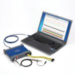
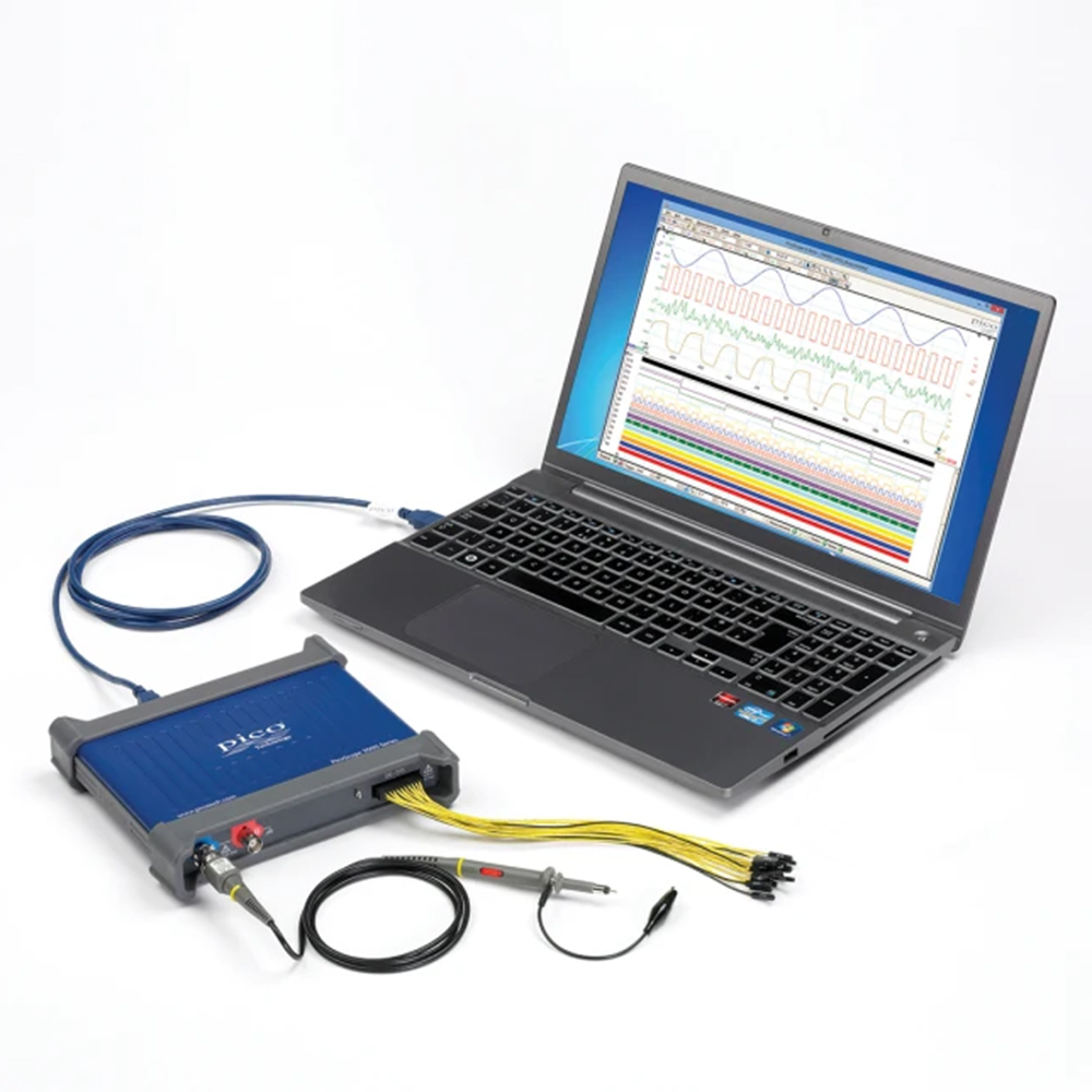
PicoScope 3000 Series USB-powered PC oscilloscopes are small, light, and portable and can easily slip into a laptop bag while offering a range of high-performance specifications.
These oscilloscopes offer 2 or 4 analog channels and a built-in function / arbitrary waveform generator. MSO models add 16 digital channels. Key performance specifications:
- 200 MHz analog bandwidth
- 1 GS/s real-time sampling
- 512 MS buffer memory
- 100,000 waveforms per second
- 16 channel logic analyzer (MSO models)
- Decode over 30 serial protocols as standard
- Arbitrary waveform generator
- USB 3.0 connected and powered
- Serial decoding and mask testing as standard
- Windows, Linux and Mac software
Supported by the advanced PicoScope software, these devices offer an ideal, cost-effective package for many applications, including embedded systems design, research, test, education, service, and repair.
High bandwidth and sampling rate
Despite a compact size and low cost, there is no compromise on performance with bandwidths up to 200 MHz. This bandwidth is matched by a real-time sampling rate of up to 1 GS/s, allowing detailed display of high frequencies. For repetitive signals, the maximum effective sampling rate can be boosted to 10 GS/s by using Equivalent Time Sampling (ETS) mode.
Other oscilloscopes have high maximum sampling rates, but without deep memory they cannot sustain these rates on long timebases. The PicoScope 3000 Series offers memory depths up to 512 million samples, more than any other oscilloscope in this price range, which enables the PicoScope 3406D MSO to sample at 1 GS/s all the way down to 50 ms/ div (500 ms total capture time).
Managing all this data calls for some powerful tools. There’s a set of zoom buttons, plus an overview window that lets you zoom and reposition the display by simply dragging with the mouse or touchscreen. Zoom factors of several million are possible. Other tools such as the waveform buffer, mask limit test, serial decode and hardware acceleration work with the deep memory making the PicoScope 3000 series some of the most powerful oscilloscopes on the market.
Mixed-signal capability / logic analyzer
The PicoScope 3000D Series Mixed-Signal Oscilloscopes include 16 digital inputs so that you can view digital and analog signals simultaneously.
The digital inputs can be displayed individually or in named groups with binary, decimal or hexadecimal values shown in a bus-style display. A separate logic threshold from –5 V to +5 V can be defined for each 8-bit input port. The digital trigger can be activated by any bit pattern combined with an optional transition on any input. Advanced logic triggers can be set on either the analog or digital input channels, or both to enable complex mixed-signal triggering.
The digital inputs bring extra power to the serial decoding options. You can decode serial data on all analog and digital channels simultaneously, giving you up to 20 channels of data. You can for example decode multiple SPI, I²C, CAN bus, LIN bus and FlexRay signals all at the same time!
Serial bus decoding and protocol analysis
PicoScope includes more serial decoders than any other oscilloscope on the market (40 and counting). All decoders are included as standard* with no optional extras required or licences to be purchased. Our regular free software updates provide new decoders as they are released.
*Ensure the bandwidth of your chosen PicoScope device is high enough to capture the signals you wish to decode.Key Features:
- Decode and display multiple protocols: You can decode multiple different protocols at the same (e.g. CAN, LIN and FlexRay). The only limit is the number of available channels. The high resolution of a PC display is perfect for such complex applications.
- Data visualization: View decoded data in hex, binary, decimal, or ASCII directly beneath the waveform on a common time axis. Error frames are highlighted in red for quick identification and can be zoomed in for a detailed investigation of noise or signal integrity issues.
- Graph format shows the decoded data beneath the waveform on a common time axis, with error frames marked in red. These frames can be zoomed to investigate noise or distortion.
- Detailed table format: See a comprehensive list of decoded frames, including all data, flags, and identifiers. Use filtering to focus on specific frames or search for frames with particular properties. The statistics option gives deeper insight into the physical layer, revealing frame times and voltage levels. Click any frame in the table to zoom into its corresponding waveform.
- Export and offline analysis: Easily export table view data for offline viewing and analysis, ensuring you can work with your data whenever and wherever you need.
- Link file feature: Accelerate your analysis by cross-referencing values to human-readable text.
- Import: PicoScope can a spreadsheet to decode the hexadecimal data into user-defined text strings.
Discover why PicoScope is the preferred choice for professionals demanding precision and efficiency in serial decoding.
Arbitrary waveform and function generator
All PicoScope 3000D units have a built-in function generator (sine, square, triangle, DC level, white noise, PRBS etc.) on the front panel. PicoScope 3000D MSO models have the connector on the rear panel.
As well as basic controls to set level, offset and frequency, more advanced controls allow you to sweep over a range of frequencies. Combined with the spectrum peak hold option this makes a powerful tool for testing amplifier and filter responses.
Trigger tools allow one or more cycles of a waveform to be output when various conditions are met such as the scope triggering or a mask limit test failing.
A 14 bit 80 MS/s arbitrary waveform generator (AWG) is also included. AWG waveforms can be created or edited using the built-in AWG editor, imported from oscilloscope traces, or loaded from a spreadsheet.
FFT spectrum analyser
The spectrum view plots amplitude against frequency, revealing details that would otherwise be hidden in an oscilloscope view. It is ideal for finding noise, crosstalk or distortion in signals. The spectrum analyzer in PicoScope is of the Fast Fourier Transform (FFT) type that, unlike a traditional swept spectrum analyzer, can display the spectrum of a single, non-repeating waveform. With up to a million points, PicoScope’s FFT has excellent frequency resolution and a low noise floor.
With a click of a button, you can display a spectrum plot of the active channels, with a maximum frequency up to the bandwidth of your scope. To focus on a specific frequency range, you can directly set the start and stop values of the analyzer frequency axis. A full range of settings gives you control over the number of spectrum bands (FFT bins), start/stop frequencies, scaling (including log/log) and display modes (instantaneous, average, or peak-hold). A selection of window functions allows you to optimize for selectivity, accuracy or dynamic range.
You can display multiple spectrum views alongside oscilloscope views of the same data. A comprehensive set of automatic frequency-domain measurements can be added to the display, including THD, THD+N, SNR, SINAD and IMD. You can even use the AWG and spectrum mode together to perform swept scalar network analysis.
The spectrum works with the waveform buffer so you can capture and rewind through thousands of spectrum plots or why not use the mask limit tests to scan through them all automatically? Spectrum masks can also work with PicoScope actions so you can leave the spectrum running continuously and choose to save mask fails to disk or even sound an alarm.
Signal integrity
Most oscilloscopes are built down to a price. PicoScopes are built up to a specification.
Careful front-end design and shielding reduces noise, crosstalk and harmonic distortion. Years of oscilloscope design experience can be seen in improved bandwidth flatness and low distortion.
We are proud of the dynamic performance of our products, and unlike most oscilloscope manufacturers publish our specifications in detail. The result is simple: when you probe a circuit, you can trust in the waveform you see on the screen.
USB connectivity 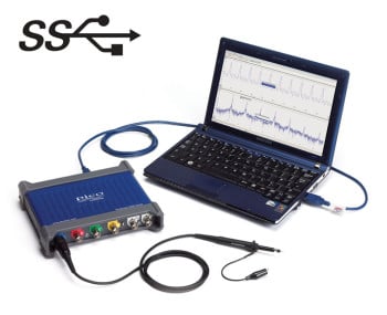
The USB connection not only allows high-speed data acquisition and transfer, but also makes printing, copying, saving, and emailing your data from the field quick and easy. USB powering removes the need to carry around a bulky external power supply, making the kit even more portable for the engineer on the move.
PicoScope 3000 Series oscilloscopes feature a SuperSpeed USB 3.0 connection, making the already-optimized process of data transfer and waveform update rates even faster. Further benefits of a USB 3.0 connection include faster saving of waveforms and faster gap-free continuous streaming of up to 125 MS/s when using the SDK, while the scope is still backward-compatible with older USB systems.
200 MHz USB 3.0 oscilloscopes with 16 channel logic analyser
Advanced digital triggering
The majority of digital oscilloscopes still use an analog trigger architecture based on comparators. This causes time and amplitude errors that cannot always be calibrated out and often limits the trigger sensitivity at high bandwidths.
In 1991 Pico pioneered the use of fully digital triggering using the actual digitized data. This technique reduces trigger errors and allows our oscilloscopes to trigger on the smallest signals, even at the full bandwidth. Trigger levels and hysteresis can be set with high precision and resolution.
The reduced rearm delay provided by digital triggering, together with segmented memory, allows the capture of a new waveform every microsecond until the buffer is full.
The PicoScope 3000 series offers an industry-leading set of advanced triggers including pulse width, windowed and dropout. In addition logic triggering allows you to trigger the scope when any or all of the 16 digital inputs match a user-defined pattern.
Hardware Acceleration Engine (HAL3)
Some oscilloscopes struggle when you enable deep memory; the screen update rate slows and controls become unresponsive. The PicoScope 3000 Series avoids this limitation with use of a dedicated hardware acceleration engine inside the oscilloscope. Its massively parallel design effectively creates the waveform image to be displayed on the PC screen and allows the continuous capture and display to the screen of over 440 million samples every second. PicoScope oscilloscopes manage deep memory better than competing oscilloscopes, both PC-based and benchtop.
The PicoScope 3000 series is fitted with third-generation hardware acceleration (HAL3). This speeds up areas of oscilloscope operation such as allowing waveform update rates in excess of 100 000 waveforms per second and the segmented memory/rapid trigger modes. The hardware acceleration engine ensures that any concerns about the USB connection or PC processor performance being a bottleneck are eliminated.
100,000 waveforms per second
Persistence mode rapidly superimposes multiple waveforms on the same view, with more frequent or newer waveforms drawn in brighter colors than older ones. This emulates the phosphor display of a conventional analog scope and is useful for displaying and interpreting complex analog signals such as video waveforms and analog modulation signals.
Hardware acceleration (HAL3) allows waveform update rates of up to 100,000 per second in Fast persistence mode – allowing you to collect thousands of waveforms per second in order to quickly spot glitches and observe jitter.
Waveform buffer and navigator
Ever spotted a glitch on a waveform, but by the time you’ve stopped the scope it has gone? With PicoScope you no longer need to worry about missing glitches or other transient events. PicoScope can store the last ten thousand oscilloscope or spectrum waveforms in its circular waveform buffer.
The buffer navigator provides an efficient way of navigating and searching through waveforms, effectively letting you turn back time. Tools such as mask limit testing can also be used to scan through each waveform in the buffer looking for mask violations.
DeepMeasure™
One waveform, millions of measurements.
Measurement of waveform pulses and cycles is key to verification of the performance of electrical and electronic devices.
Deep Measure delivers automatic measurements of important waveform parameters, such as pulse width, rise time and voltage. Up to a million cycles can be displayed with each triggered acquisition. Results can be easily sorted, analyzed and correlated with the waveform display
Mask limit testing
Mask limit testing allows you to compare live signals against known good signals, and is designed for production and debugging environments. Simply capture a known good signal, draw a mask around it, and then attach the system under test. PicoScope will check for mask violations and perform pass/fail testing, capture intermittent glitches, and can show a failure count and other statistics in the Measurements window.
Actions
PicoScope can be programmed to execute actions when certain events occur.
The events that can trigger an alarm include mask limit fails, trigger events and buffers full.
The actions that PicoScope can execute include saving a file, playing a sound, executing a program or triggering the signal generator / AWG.
Actions, coupled with mask limit testing, help create a powerful and time saving waveform monitoring tool. Capture a known good signal, auto generate a mask around it and then use the alarms to automatically save any waveform (complete with a time/date stamp) that does not meet specification.
High-end features as standard
Buying a PicoScope is not like making a purchase from other oscilloscope companies, where optional extras considerably increase the price. With our scopes, high-end features such as serial decoding, mask limit testing, advanced math channels, segmented memory, and a signal generator are all included in the price.
To protect your investment, both the PC software and firmware inside the scope can be updated. Pico Technology have a long history of providing new features for free through software downloads. We deliver on our promises of future enhancements year after year, unlike many other companies in the field. Users of our products reward us by becoming lifelong customers and frequently recommending us to their colleagues.
Order code / Model number
| PicoScope 3203D | 50 MHz 2-channel oscilloscope |
| PicoScope 3203D MSO | 50 MHz 2-channel mixed-signal oscilloscope |
| PicoScope 3204D | 70 MHz 2-channel oscilloscope |
| PicoScope 3204D MSO | 70 MHz 2-channel mixed-signal oscilloscope |
| PicoScope 3205D | 100 MHz 2-channel oscilloscope |
| PicoScope 3205D MSO | 100 MHz 2-channel mixed-signal oscilloscope |
| PicoScope 3206D | 200 MHz 2-channel oscilloscope |
| PicoScope 3206D MSO | 200 MHz 2-channel mixed-signal oscilloscope |
| PicoScope 3403D | 50 MHz 4-channel oscilloscope |
| PicoScope 3403D MSO | 50 MHz 4-channel mixed-signal oscilloscope |
| PicoScope 3404D | 70 MHz 4-channel oscilloscope |
| PicoScope 3404D MSO | 70 MHz 4-channel mixed-signal oscilloscope |
| PicoScope 3405D | 100 MHz 4-channel oscilloscope |
| PicoScope 3405D MSO | 100 MHz 4-channel mixed-signal oscilloscope |
| PicoScope 3406D | 200 MHz 4-channel oscilloscope |
| PicoScope 3406D MSO | 200 MHz 4-channel mixed-signal oscilloscope |
Accessories
 |
Passive oscilloscope probe: 100 MHz bandwidth 1:1/10:1 switchable, BNC |
 |
Passive oscilloscope probe: 200 MHz bandwidth 1:1/10:1 switchable, BNC |
 |
Replacement spring probe tips, 5 pack |
 |
Replacement rigid probe tips, 5 pack |
 |
Logic test clips, pack of 10 |
 |
20-way digital input cable for MSOs |
 |
25 MHz 700 V differential oscilloscope probe 10:1/100:1 |
|
25 MHz 1400 V differential oscilloscope probe 20:1/200:1 |
 |
50 MHz 70 V differential oscilloscope probe 10:1 |
 |
70 MHz 7000 V differential oscilloscope probe 100:1/1000:1 |
 |
100 MHz 700 V differential oscilloscope probe 10:1/100:1 |
 |
100 MHz 1400 V differential oscilloscope probe 100:1/1000:1 |
 |
200 MHz 20 V differential oscilloscope probe 10:1 |
 |
30 A AC/DC precision current probe, BNC connector |
 |
60 A AC/DC current probe, BNC connector |
 |
200 A / 2000 A AC/DC current probe, BNC connector |
 |
600 A AC/DC current probe, BNC connector |
 |
Three-axis accelerometer and oscilloscope interface |
 |
Terminator: feed-through, 1 GHz 50 Ω 1 W BNC (m-f) |
 |
Attenuator set: 3-6-10-20 dB, 1 GHz 50 Ω 1 W BNC (m-f) |
 |
BNC plug to 4 mm (banana) plug cable, 1.2 m |
 |
BNC to BNC cable, 1.1 m |
 |
Small crocodile clip, red |
|
Small crocodile clip, black |
 |
Large dolphin clip, 1000 V CAT III, red |
|
Large dolphin clip, 1000 V CAT III, black |
 |
Sprung hook probe 1000 V CAT III, red |
|
Sprung hook probe 1000 V CAT III, black |
 |
Multimeter probe, 1000 V CAT II, red |
|
Multimeter probe, 1000 V CAT II, black |
 |
USB 3.0 cable, 1.8 m TA155 |
 |
Hard carry case – medium |
 |
USB 2.0 Y-cable, 1.8 m |
 |
5 V AC power adaptor |
 |
Calibration certificate for PicoScope oscilloscopes: 2000, 3000, 4000 (excl. 4824 and 4444) |