Online Buying Store
Request for Quote Store
{{minicart.wishlist.length}} {{minicart.cartList.length}}
You have no items in your shopping cart.
You have 1 item in your shopping cart.
{{multiCartItemsStr.replace('[COUNT]', minicart.cartList.length)}}
{{cartItem.ProductName}}
  • {{itemVariant.VariantHasText ? (itemVariant.VariantName + ': ' + itemVariant.VariantText) : (itemVariant.VariantGroup + ': ' + itemVariant.VariantName)}}
Total: {{cartItem.UnitCost * cartItem.Quantity | currency : 'R' : 2}}
Qty: {{cartItem.Quantity | number : 2}}

Item Qty Total
{{cartItem.ProductName}} {{cartItem.ProductName}}
SKU: {{cartItem.ProductSku}}
{{cartItem.Quantity | number : 2}} x {{cartItem.UnitCost | currency : 'R' : 2}}
{{cartItem.UnitCost * cartItem.Quantity | currency : 'R' : 2}}
  • {{itemVariant.VariantHasText ? (itemVariant.VariantName + ': ' + itemVariant.VariantText) : (itemVariant.VariantGroup + ': ' + itemVariant.VariantName)}}
You have no items in your shopping cart.
Subtotal {{minicart.cartTotals.SubTotal | currency : 'R' : 2}}
Image Item Qty Total
{{cartItem.ProductName}} {{cartItem.ProductName}}
SKU: {{cartItem.ProductSku}}
{{cartItem.Quantity | number : 2}} x {{cartItem.UnitCost | currency : 'R' : 2}}
{{cartItem.UnitCost * cartItem.Quantity | currency : 'R' : 2}}
  • {{itemVariant.VariantHasText ? (itemVariant.VariantName + ': ' + itemVariant.VariantText) : (itemVariant.VariantGroup + ': ' + itemVariant.VariantName)}}
You have no items in your shopping cart.
Description Created
{{savedCart.Description}} {{savedCart.CreateDate | date : 'yyyy-MM-dd HH:mm'}}
SKU Product Name Unit Cost Qty Line Total
{{cartItem.ProductSku}} {{cartItem.ProductName}} {{cartItem.UnitCost | currency : 'R' : 2}} {{cartItem.Quantity | number : 2}} {{cartItem.UnitCost * cartItem.Quantity | currency : 'R' : 2}}
  • {{itemVariant.VariantHasText ? (itemVariant.VariantName + ': ' + itemVariant.VariantText) : (itemVariant.VariantGroup + ': ' + itemVariant.VariantName)}}
You have no items in your saved shopping cart.
You have no items in your wishlist.
Status Order No. Order Date Ship To Order Total Pay Total Balance
Bill Me Later Open Ready To Ship Shipped Picked Up Cancelled Incomplete On Hold Back Ordered Returned {{order.Status}}
{{order.OrderID}} {{order.OrderDate | date : 'yyyy-MM-dd'}} {{order.ShipFirstName}} {{order.ShipLastName}}, {{order.ShipAddress1}} {{order.ShipAddress2}}, {{order.ShipCity}}, {{order.ShipState}} {{order.ShipZipcode}} {{order.GrandTotal | currency : 'R' : 2}} {{order.PayTotal | currency : 'R' : 2}} {{order.GrandTotal - order.PayTotal | currency : 'R' : 2}}
Logo

Comtest Paid Store

Grid View List View Sorting: Normal Sorting: Price Low to High Sorting: Price High to Low Sorting: New Arrivals Sorting: Brand A-Z Sorting: Brand Z-A
Fluke 179 Promotion

Fluke 179 True RMS DMM

sku Product SKU:  FLK-179

The Fluke 179 True-RMS DMM is the industry-standard troubleshooting tool for electrical and electronic systems.

With its precision, reliability, and ease of use, the Fluke 179 is the preferred solution for professional technicians around the world. It includes the features you need to troubleshoot and repair electrical and electronic systems, plus a backlit digital display, analog bar graph, and built-in temperature measurements.

Works When You Need It, Where You Need It

You can trust the rugged reliable Fluke 179 to get the job done in all of the messy, loud, high energy, and high altitude places you work. Whether you need a multimeter for industrial troubleshooting or electrical and electronic system installation or maintenance, the Fluke 179 with its true-RMS capabilities can do the job. It is independently tested for safe use in CAT III 1000 V, CAT IV 600 V environments and backed by a lifetime warranty

Just One of Fluke's Trusted Tools

Fluke builds the most trusted tools in the world, which means more than just the Fluke 179. If you work with HVAC equipment, work in the electrical installer's and repairman's world or need a small meter for small spaces, check out the full family of Fluke digital multimeters.

Other useful features:

  • Safety rated CAT III 1000 V, CAT IV 600 V
  • Comes with a lifetime warranty
  • Allows closed-case calibration through front panel
  • Includes ergonomic case with integrated protective holster

ZAR 13478,0000

FLK-88V

Fluke 88V Deluxe Automotive Multimeter

sku Product SKU:  FLK-88V

The Fluke 88V meter has measurement functions, troubleshooting features, and accuracy levels needed to solve problems on conventional and hybrid vehicles. The 88V is the most powerful automotive multimeter ever offered by Fluke. In addition to standard multimeter features such as the ability to measure voltage, current, continuity, and resistance, the 88V can perform:

Pulse width

Duty cycle

Min/Max/Average recording

Diode tests

The pulse width function provides millisecond resolution for troubleshooting fuel injectors.

Automotive measurements

The 88V meter can take care of many automotive needs, getting into more of the digital multimeters measurement capabilities - it can measure voltage up to 1000 V AC and DC, current up to 10 A, 20 A for up to 30 seconds and frequency to 200 kHz and % duty cycle. Add those features to RPM measurements with optional inductive pickup and millisecond pulse width measurements for fuel injectors to name a few. The 88V comes packed with the functions you need:

Temperature measurements with optional temperature probe

Analog bar graph to track changing or unstable signals

Min/Max/Average recording with Min/Max Alert to capture variations automatically

Peak Min/Max to record transients as fast as 250 μs

88V multimeter designed for the garage

While working in a garage, the large display digits can help you focus on the vehicle while still being able to read the numbers. Plus, the two-level bright white backlight offers the additional visibility you may need.

An optional magnetic hanger lets you hang the meter from most steel surfaces for easy set-up and viewing. The 88V is designed to be used in high energy environments like those found on hybrid vehicles.

The product is supported by a limited lifetime warranty.

ZAR 26490,0000

FLK-709H

Fluke 709H Precision Loop Calibrator with HART Communications / Diagnostics

sku Product SKU:  FLK-709H

The Fluke 709H mA loop calibrator is designed to save time and produce high-quality results. It includes HART communication and supports a select set of the HART universal and common practice commands. This makes the 709H unique as both an affordable, compact loop calibrator and powerful HART communication tool that offers:

  • Fast transfer of calibration data: The optional 709H/Track software/cable can document the parameters of all the HART transmitters in your plant, in either (.csv) or (.txt) format
  • Data logging or recording data on a particular transmitter for troubleshooting: The data log tool offers a selectable capture interval from 1 to 60 seconds and a logging capacity of 9800 records or 99 individual sessions. Each data sample contains the 709H measurement, all four process variables, and the standard status conditions.

In the communicator mode the user can read basic device information, perform diagnostic tests, and trim the calibration on most HART-enabled transmitters. In the past, this could only be done with a dedicated communicator, a high-end multifunction calibrator, or a laptop computer with HART modem. The Fluke 709H will allow virtually any technician to service and support HART devices.

And it's easy to use. The Fluke 709H is built around a user-friendly interface with a Quick-Set rotary encoder knob. This reduces the time it takes to measure or source voltage or current, and power up a loop. The protective holster easily fits into a technician's hand and the large backlit display is easy to read, even in dark, cramped worked areas.

ZAR 53990,0000

Fluke-125B-app

Fluke ScopeMeter Portable Oscilloscopes 120B Series

sku Product SKU:  FLK-120BS

Simplified testing, more insight, and faster electro-mechanical troubleshooting

The compact ScopeMeter® 120B Series is the rugged oscilloscope solution for industrial electrical and electro-mechanical equipment troubleshooting and maintenance applications. It's a truly integrated test tool, with an oscilloscope, multimeter, and high-speed recorder in one easy-to-use instrument. The ScopeMeter 120B Series also integrates with Fluke Connect® mobile app and FlukeView® for ScopeMeter software to enable further collaboration, data analysis, and archiving of critical test information.

*Not all models are available in all countries. Check with your local Fluke representative.

Other useful features:

  • Features two 5,000-count True-RMS digital multimeters
  • Offers recorder Event Detect to capture elusive intermittent signals on repetitive waveforms up to 4 kHz
  • Comes with shielded test leads for oscilloscope, resistance and continuity measurements
  • Features resistance, continuity, diode, and capacitance meter measurements
  • Performs power measurements (W, VA, VAR, PF, DPF, Hz)
  • Measures voltage, current and power harmonics
  • Check Industrial networks with BusHealth physical layer tests against defined reference levels (125B only)
  • Allows you to save and recall data and instrument setups
  • Includes FlukeView® ScopeMeter® software for Windows®
  • Features a rugged design to withstand 3g vibration, 30g shock, and rated IP51 according to EN/IEC60529
  • Runs on a Li-Ion rechargeable battery providing seven-hours operation (with four-hour charge time)
  • Features highest safety rating in the industry: safety rated for CAT IV 600 V

ZAR 59890,0000

FLK-1736-1738

Fluke 1736 and 1738

sku Product SKU:  FLK-173x-EUS

The Fluke 1736 and 1738 Three-Phase Power Loggers built with Fluke Connect® mobile app and desktop software compatibility give you the data you need to make critical power quality and energy decisions in real-time. The ideal test tools for conducting energy studies and basic power quality logging, the 1736 and 1738 automatically capture and log over 500 power quality parameters so you have more visibility into the data you need to optimize system reliability and savings. With the Fluke 1738 Advanced Power Logger you can perform advanced analysis with an enhanced Power Quality Health Summary (EN50160) function that provides you with fast insight into overall electrical system health. The Power Quality Health Summary is an evaluation of the logged data based on detailed power quality measurements and includes viewable event waveform captures so you have even more visibility into the data you need to optimize system reliability and savings.

An optimized user interface, flexible current probes, and an intelligent measurement verification function that allows you to reduce measurement errors by digitally verifying and correcting common connection errors makes setup easier than ever and reduces measurement uncertainty. Access and share data remotely with your team via the Fluke Connect® app so you can maintain safer working distances and make critical decisions in real-time, reducing the need for protective equipment, site visits and check-ins. You can also quickly and easily chart and graph measurements to help identify issues and create detailed reports with the included Fluke Energy Analyze Plus software package. Optionally, you can create IEEE519 Reports giving you more insight into harmonic levels, voltage and current distortion, and load current (license required).

Log the most common parameters

Designed to measure the most critical three phase power parameters, the 1736 and 1738 can simultaneously log rms voltage, rms current, voltage and current events, voltage and current THD, voltage and current harmonics up to the 50th harmonic, active power, reactive power, power factor, active energy, reactive energy, and more. With enough memory for more than a year of data logging, the 1736 and 1738 can uncover intermittent or hard-to-find issues that might otherwise have been missed.

Analysis and Reporting

Capturing logged data is just one part of the task. Once you have the data, you need to create useful information and reports that can be easily shared and understood by your organization or customers. Fluke Energy Analyze Plus software makes that task as simple as possible. With powerful analysis tools and the ability to create customized reports in minutes you’ll be able to communicate your findings and quickly solve problems so you can optimize system reliability and savings.


ZAR 155990,0000

FLK-T6-600

Fluke T6-600

sku Product SKU:  FLK-T6-600

Measure voltage... without test leads

Working in cramped electrical boxes and trying to find a safe metallic contact point is often challenging. The Fluke T6-600 Electrical Tester with FieldSense™ technology, lets you quickly and safely take measurements by sliding the open fork over a conductor, without the need for test leads. The T6-600 works with wires up to AWG 4/0 (120 mm2) with a 17.8 mm jaw opening

How FieldSense™ technology works

FieldSense™ technology is a breakthrough in how voltage is measured. Other open fork testers detect a magnetic field to show AC current. FieldSense™ technology detects an electrical field, which interacts with a reference signal created by the T6 tester, which shows the measurement value on the tester's display.

Tips on using FieldSense technology

  • Do not hold or touch wire you are testing during a measurement.
  • Use the black probe to make the ground connection if you are wearing gloves, insulated footwear or standing on an insulated ladder

Measurement versatility

The electrical tester offers a variety of measurement options giving you an all-in-one troubleshooting tool. Measure true rms voltage and current from 0 to 200 A AC or 1 to 600 V AC or DC. You can also gather resistance measurement from 1 Ω to 2000 Ω. With the easy-to-read backlit display, you can keep see your work in dark environments and keep your most recent measurement on the screen with the HOLD button for easy viewing. The T6-600 also accepts optional Fluke TPAK Magnetic Meter Hanger for convenient operation.

ZAR 7490,0000

Fluke 805FC

sku Product SKU:  FLK-805FC

The reliable, repeatable, accurate way to check bearings and overall vibration

Make go or no-go maintenance decisions with confidence. The Fluke 805 FC Vibration Meter is the most reliable vibration screening device available for frontline mechanical troubleshooting teams that need repeatable, severity-scaled readings of overall vibration and bearing condition.

Other useful features:

  • Allows you to export data via USB
  • Compatible with Fluke Connect® Mobile App that can transmit measurements to your smartphone to be shared in real time
  • Enables you to get authorization to take next steps in an instant if machine health is at risk via Fluke Connect™ Share-Live™ video call*
  • Allows you to view trending in Microsoft® Excel using pre-built templates
  • Measures overall vibration (10 Hz to 1,000 Hz) for acceleration, velocity, and displacement units of measurement for a wide variety of machines
  • Provides Crest Factor+ technology for reliable bearing assessment using direct sensor tip measurements between 4,000 Hz and 20,000 Hz
  • Compares vibration levels with ISO-10816 severity scales and stores results to the Fluke Connect Cloud
  • Features colored lighting system (green, red) and on-screen comments to indicate how much pressure needs to be applied to take measurements
  • Measures temperature with Spot IR Sensor to increase diagnostic capabilities
  • Holds and saves up to 3,500 measurements in on-board memory
  • Provides external accelerometer support for hard to reach locations
  • Features built-in flashlight for viewing measurement locations in dark areas
  • Provides large high-resolution display for easy navigation and viewing

ZAR 65990,0000

Optris BR 400

sku Product SKU:  OPT-BR400

Knowing the exact value of the radiation temperature is essential for the calibration process. It can be measured by either using a contact thermometer (in combination with the determination of the emissivity) or a transfer standard infrared thermometer. This value can then be used to determine the device constant for an initial calibration of the infrared sensors. In order to conduct a post-calibration by customers or local calibration facilities, the calibration temperature should be near the temperatures which occur at the respective applications.

Optris makes use of a transfer standard radiation thermometer CTlaser-PTB (see figure) to measure the radiation temperature of a reference source. The CTlaser- PTB is based on the IR thermometer optris CTlaser. The CTlaser-PTB needs to be traceable to the international temperature scale from 1990 (ITS-90). Thus, it is calibrated by the PTB (German national metrology institute) on a regular basis. ITS-90 is a very good approximation of thermodynamic temperature. It is based on 17 well-reproducible fixed values such as melting points of highly pure metals. Within the framework of ITS-90 the CTlaser-PTB is compared to national temperature standards from the PTB. This comparison within a closed chain of comparative measurements with a known uncertainty in measurement takes place on a regular basis.

Based on the CTlaser-PTB, Optris produces the CTlaser- DCI as a high-precision reference IR thermometer for its customers. The DCI units are produced with pre-selected components supporting high stability of measurement. In combination with a dedicated calibration at several calibration points the CTlaser-DCI achieves a higher accuracy than units from series production.

The optics of an IR thermometer is described by the distance-to-spot-ratio (D:S). Depending on the quality of the optics a certain amount of radiation is also received from sources outside the specified measurement spot. The maximum value here equals the radiation emitted by a hemispheric radiant source. The respective signal change in correlation with a resize of the radiation source is described by the Size-of-source effect (SSE).

As a result of this correlation all manufacturers of IR thermometers use accurately defined geometries for the calibration of their units; meaning depending on the aperture of the radiation source (A) a distance (a) between the IR thermometer and the reference source is defined. Thus, the value specified in datasheets and technical documentation as a measurement field is, in general, a certain defined percentage of this radiation maximum – values of 90 % or 95 % are common.

ZAR 54080,0000

W-PIC-6000s-1

PicoScope 6000E Series

sku Product SKU:  PIC-6000E-s

Take advantage of best-in-class bandwidth, sampling rate and memory depth.

Power, portability and performance   Flexibility without compromise

The PicoScope 6000E Series oscilloscopes are as powerful as any traditional scope, with the advantage of a small form that fits easily on your desk. The 6000E Series has oscilloscopes with up to 3 GHz bandwidth, FlexRes® models with up to 12-bit resolution (up to 16-bit with resolution enhancement enabled), plus up to 4 GS of memory - the deepest as standard in its class. With up to eight analogue channels plus 16 digital channels and an arbitrary waveform generator able to produce up to 50 MHz signals, the PicoScope 6000E Series can ably rise to any task. 

The ultra-deep memory, combined with 40 serial decoders included as standard, creates an oscilloscope that excels at debugging and monitoring digital systems. At the same time, the careful analogue design creates a front end with 60 dB of SFDR, excellent pulse response and minimal crosstalk.

ll of these features are accessible through the free PicoScope software, with regular updates, lifelong technical support and no hidden costs.


The PicoScope 6000E Series works with PicoScope 7, PicoSDK®, or PicoLog 6. Combine masks, advanced digital triggers, automated measurements, and actions with up to 40.000 waveforms stored in the buffer to spot rare timing errors, glitches, and dropouts during long tests with no coding required. Or, use the PicoSDK to create your own applications from scratch.

Unlike old-fashioned SCPI interfaces, our C-based DLLs gives access to every single part of the hardware and can stream up to 312 million samples per second. Integrate a PicoScope 6000E Series oscilloscope into your setup and use the advanced triggers and precise (single sample resolution) trigger timestamping to monitor system performance with no false positives or negatives.

The PicoScope 6000E's ultra-deep memory is managed on-device with features such as downsampling and data aggregation to reduce latency, while retaining the original capture data if more detailed analysis is required.


ZAR 271317,0000

Pico Data Loggers ADC-20 and ADC-24

sku Product SKU:  PIC-ADC-20|24

The ultimate in resolution and accuracy

With up to 24-bit resolution the ADC-20 and ADC-24 USB data loggers are able to detect small signal changes. Features such as true differential inputs, galvanic isolation and software-selectable sampling rates all contribute to a superior noise-free resolution and ensure that your measurements are reliable and accurate.

PicoLog 6  software – straightforward from the start

All Pico data acquisition products come complete with PicoLog 6. This powerful yet flexible data acquisition software allows you to collect, manipulate, analyze, display and export data. 

Designed from the ground up to be intuitive from the outset, PicoLog 6 allows you to set up the logger and start recording with just a few clicks of the mouse, whatever your level of data logging experience.

From here, starting a capture is simple: plug in the logger, add a channel, press Record, and you’re logging! PicoLog 6 also includes a number of additional features to cater for more advanced data logging needs. 

Flexible, multichannel data acquisition

Both the ADC-20 and ADC-24 feature true differential inputs for excellent noise rejection. To give you a very flexible system each differential input can also be configured as two single-ended inputs. With up to eight differential or 16 single-ended inputs on the ADC-24, this flexibility gives you complete control on what type of inputs you use. If you require more channels, you can use multiple PicoLog data loggers on the same PC.

With seven bipolar voltage ranges, the ADC-20 and ADC-24 are also flexible enough to be used with a wide range of sensors and signal types. There's also an external terminal board with screw terminals to allow you to quickly connect and disconnect different sensors.

Additionally, the ADC-24 has four configurable digital input/output channels that can be used to control alarms or other devices.

The flexibility of the ADC-20 and ADC-24 allows you to use these precision data loggers as an advanced multichannel data acquisition system with a low cost per channel.

No need for power supplies or batteries

The high-resolution ADC-20 and ADC-24 are powered directly by your PC — eliminating the need for batteries or a separate power supply, and making them ideal when you need a portable data logger.

The answer to your data acquisition needs

High resolution, true differential inputs, galvanic isolation, and selectable sampling rates combine to ensure that your measurements are always precise and accurate. Configurable inputs, digital inputs and outputs, and programmable voltage ranges give you a truly flexible answer to your data acquisition needs.

When you need the ultimate in high resolution and accuracy, the versatile ADC-20 and ADC-24 provide you with a portable answer with the performance and flexibility you need.

ZAR 7706,0000

PicoLog CM3

sku Product SKU:  PIC-LOGCM3

Typical applications

  • Mains current monitoring 
  • Three-phase load balancing
  • Long-term energy use recording
  • Energy and cost saving / ISO14001 monitoring


Screenshot of PicoLog 6 software in Windows, shows a graph of 3 current channels over time.

Flexible, expandable software included

Your PicoLog CM3 Current Data Logger is supplied with PicoLog 6 data logging software, available for Windows, macOS and Linux. With PicoLog 6 you can collect almost unlimited datasets, analyze them and then display the results in spreadsheet and graphical formats.

PicoLog 6 can record data from multiple PicoLog data loggers at the same time. This allows you to collect up to 60 channels of current. You can even mix and match different PicoLog loggers to record a mix of current, temperature, voltage and other signals.

The PicoSDK, a software development kit (SDK) is also supplied. PicoSDK contains a range of software drivers and example code that you can use to write your own software or to use your PicoLog CM3 with third-party software such as MATLAB, C,C++, C#, LabVIEW, Python, VB, VB.net to name but a few. PicoSDK can be found on GitHub.

Both PicoLog 6 and PicoSDK are provided free of charge and updates can be downloaded for free.


Image shows a blue and black current clamp with jaws closed

Non-invasive current clamps

The PicoLog CM3 measures current using industry-standard AC current clamps. These clamps have opening jaws so can be installed in seconds with no physical connection to high voltages. AC current clamps require no power supply or batteries so are ideal for long-term energy-use monitoring and logging.

Pico supply 200 A AC current clamps as standard. If you need to measure higher currents we will be happy to advise on suitable clamps for your application.

The PicoLog CM3 is available on its own so you can add your own current clamps or as a cost-saving kit with three 200 A clamps included.


Image shows the rear panel of the PicoLog CM3 showing Ethernet and USB ports

USB or Ethernet connection for local or remote logging

With both USB and Ethernet interfaces your PicoLog CM3 can be used in a variety of situations. If you need a portable instrument that can be used at various locations and is fast to set up and use, simply connect your laptop to the PicoLog CM3 by USB.  No external power supply is required as the CM3 is powered from the USB port.

Need to monitor a situation over a period of hours or days, or from a remote location? Plug your PicoLog CM3 into a spare port on your network and then access it remotely either from your LAN or over the internet. When using Ethernet the CM3 can be powered either by Power over Ethernet (PoE) or by using the USB connection just for power.

ZAR 9711,0000

PICO USB TC-08

sku Product SKU:  PIC-TC-08

8 channel thermocouple data logger

  • 8 channel thermocouple data logger
  • Measures from –270 to +1820 °C (–454 to +3308 °F)
  • High resolution and accuracy
  • Expandable to 20 units / 160 channels
  • Supports all popular thermocouple types
  • Fast sampling rate — up to 10 measurements per second (including CJC)
  • USB connected and powered
  • PicoLog 6 for Windows, macOS and Linux data logging software included
  • PicoSDK drivers for Windows, macOS and Linux included


Wide temperature range

The TC-08 thermocouple data logger is designed to measure a wide range of temperatures using any thermocouple that has a miniature thermocouple connector. Pico supply a wide range of suitable thermocouples (see Accessories).

All popular types of thermocouple are supported, allowing an effective temperature range of –270 to +1820 °C  (the actual temperature range depends on the thermocouple being used).

The built in Cold Junction Compensation (CJC) circuit can also be used as a 9th channel to measure room temperature.


Fast and accurate temperature data acquisition

With the TC-08 thermocouple data logger your temperature measurements can be made both fast and accurately.

The short conversion time of the TC-08 means up to 10 temperature measurements can be taken every second (cold junction compensation counts as an additional measurement), while the high (20-bit) resolution ensures that the TC-08 can detect minute changes in temperature.  For popular Type K thermocouples the TC-08 can maintain a better than 0.025°C resolution over a –250 to +1370 °C range.


terminal board for TC-08 data logger

Also measure voltage and 4–20 mA current loops!

As well as measuring temperature with thermocouples, the terminal board allows other sensors with voltage or current outputs to be connected.  

The optional Single-Channel Terminal Board (see Accessories) plugs into a channel on the TC-08 and turns it into a 20-bit high resolution data logger. Screw terminals allow wires to be attached to the data logger without soldering. The four input ranges (±50 mV, ±500 mV, ±5 V and 4-20 mA) allow a wide range of other sensors and signals to be measured.


TC-08 thermocouple data logger

All you need in one easy-to-use unit

Temperature data acquisition with the TC-08 is very easy — simply plug the TC-08 into a USB port on your computer (no external power required), connect your thermocouples, and you are ready to measure temperatures.

The easy-to-use PicoLog data acquisition software is supplied with the TC-08 — allowing you to start measuring and recording temperatures with the minimum effort. The intuitive user interface of PicoLog makes it easy for you to set how frequently you want to take a measurement, and the number of measurements you want to take.


Need more?...

If you need more than 8 channels just plug up to 20 TC-08s into a powered USB hub network connected to your PC for a total of 160 channels. You can even mix and match different data loggers and a selection of PicoScope oscillsocopes from the Pico range to build a flexible, expandable data acquisition system.

ZAR 9711,0000

Pico TA386 Passive probe

sku Product SKU:  PIC-TA386

Passive oscilloscope probes

Our ergonomically designed passive oscilloscope probes are suitable for use with all major brands of oscilloscopes as well as the PicoScope range of USB Oscilloscopes. Passive probes don't require a power supply or batteries so are lightweight and easily portable.

Read our free guide: How to Tune x10 Oscilloscope Probes.

Passive oscilloscope probe: 200 MHz bandwidth 1:1/10:1 switchable, BNC

The TA386 is a passive switchable oscilloscope probe, with a bandwidth of 200 MHz. This probe is an upgraded version of our TA131 which includes many improvements to enhance durability, ease of use and performance, such as:

  • Redesigned probe tip allows removal and refitting of replacement tips
  • Replacement TA385 spring tips and TA384 rigid tips are available separately
  • Redesigned probe hook accessory fitting
  • Upgraded high durability probe cable

A passive oscilloscope probe with BNC connector with it's kit contents, cable coiled up.

ZAR 945,0000

PicoScope-3000

PicoScope 3000 Series

sku Product SKU:  PIC-3000-S

PC Oscilloscopes & Mixed Signal Oscilloscopes

PicoScope 3000 mixed signal oscilloscopes

Power, portability and performance

PicoScope 3000 Series USB-powered PC oscilloscopes are small, light, and portable and can easily slip into a laptop bag while offering a range of high-performance specifications.

These oscilloscopes offer 2 or 4 analog channels and a built-in function / arbitrary waveform generator. MSO models add 16 digital channels. Key performance specifications:

  • 200 MHz analog bandwidth
  • 1 GS/s real-time sampling
  • 512 MS buffer memory
  • 100,000 waveforms per second
  • 16 channel logic analyzer (MSO models)
  • Arbitrary waveform generator
  • USB 3.0 connected and powered
  • Serial decoding and mask testing as standard
  • Windows, Linux and Mac software

Supported by the advanced PicoScope 6 software, these devices offer an ideal, cost-effective package for many applications, including embedded systems design, research, test, education, service, and repair.
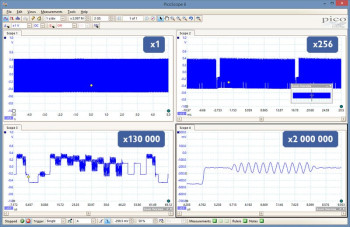
deep memory oscilloscope showing zoom

High bandwidth and sampling rate

Despite a compact size and low cost, there is no compromise on performance with bandwidths up to 200 MHz.  This bandwidth is matched by a real-time sampling rate of up to 1 GS/s, allowing detailed display of high frequencies. For repetitive signals, the maximum effective sampling rate can be boosted to 10 GS/s by using Equivalent Time Sampling (ETS) mode.

Other oscilloscopes have high maximum sampling rates, but without deep memory they cannot sustain these rates on long timebases. The PicoScope 3000 Series offers memory depths up to 512 million samples, more than any other oscilloscope in this price range, which enables the PicoScope 3406D MSO to sample at 1 GS/s all the way down to 50 ms/ div (500 ms total capture time).

Managing all this data calls for some powerful tools. There’s a set of zoom buttons, plus an overview window that lets you zoom and reposition the display by simply dragging with the mouse or touchscreen. Zoom factors of several million are possible.  Other tools such as the waveform buffer, mask limit test, serial decode and hardware acceleration work with the deep memory making the PicoScope 3000 series some of the most powerful oscilloscopes on the market.

Mixed-signal capability / logic analyzer

The PicoScope 3000D Series Mixed-Signal Oscilloscopes include 16 digital inputs so that you can view digital and analog signals simultaneously.

The digital inputs can be displayed individually or in named groups with binary, decimal or hexadecimal values shown in a bus-style display. A separate logic threshold from –5 V to +5 V can be defined for each 8-bit input port. The digital trigger can be activated by any bit pattern combined with an optional transition on any input. Advanced logic triggers can be set on either the analog or digital input channels, or both to enable complex mixed-signal triggering.

The digital inputs bring extra power to the serial decoding options.  You can decode serial data on all analog and digital channels simultaneously, giving you up to 20 channels of data.  You can for example decode multiple SPI, I²C, CAN bus, LIN bus and FlexRay signals all at the same time!

Application note: Debugging an I²C Bus with a PicoScope Mixed–Signal Oscilloscope

Mixed Signal Oscilloscope / Logic Analyzer (roll over red circles for description)


CAN bus serial decoding

Serial bus decoding and protocol analysis

PicoScope can decode 1-WireARINC 429CAN & CAN-FDDCC, DMX512, Ethernet 10Base-T and 100Base-TX,  FlexRay, I²C, I²S, LIN, PS/2, MODBUSSENTSPIUART (RS-232 / RS-422 / RS-485), and USB 1.1 protocol data as standard, with more protocols in development and available in the future with free-of-charge software upgrades.

Graph format shows the decoded data (in hex, binary, decimal or ASCII) in a data bus timing format, beneath the waveform on a common time axis, with error frames marked in red. These frames can be zoomed to investigate noise or signal integrity issues.

Table format shows a list of the decoded frames, including the data and all flags and identifiers. You can set up filtering conditions to display only the frames you are interested in or search for frames with specified properties. The statistics option reveals more detail about the physical layer such as frame times and voltage levels. PicoScope can also import a spreadsheet to decode the data into user-defined text strings.

More information on Serial bus decoding and protocol analysis - overview >>

PicoScope arbitrary waveform generator

Arbitrary waveform and function generator

All PicoScope 3000D units have a built-in function generator (sine, square, triangle, DC level, white noise, PRBS etc.) on the front panel. PicoScope 3000D MSO models have the connector on the rear panel.

As well as basic controls to set level, offset and frequency, more advanced controls allow you to sweep over a range of frequencies. Combined with the spectrum peak hold option this makes a powerful tool for testing amplifier and filter responses.

Trigger tools allow one or more cycles of a waveform to be output when various conditions are met such as the scope triggering or a mask limit test failing.

A 14 bit 80 MS/s arbitrary waveform generator (AWG) is also included. AWG waveforms can be created or edited using the built-in AWG editor, imported from oscilloscope traces, or loaded from a spreadsheet.

More information on Arbitrary waveform generator (AWG) >>
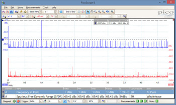
Spectrum analyzer: Multiple spectrum views

FFT spectrum analyzer

The spectrum view plots amplitude against frequency and is ideal for finding noise, crosstalk or distortion in signals. The spectrum analyzer in PicoScope is of the Fast Fourier Transform (FFT) type which, unlike a traditional swept spectrum analyzer, can display the spectrum of a single, non-repeating waveform.

A full range of settings gives you control over the number of spectrum bands (FFT bins), window types, scaling (including log/log) and display modes (instantaneous, average, or peak-hold).

You can display multiple spectrum views alongside oscilloscope views of the same data. A comprehensive set of automatic frequency-domain measurements can be added to the display, including THD, THD+N, SNR, SINAD and IMD. A mask limit test can be applied to a spectrum and you can even use the AWG and spectrum mode together to perform swept scalar network analysis.

More information on Spectrum analyzer >>

oscilloscope front end shielding

Signal integrity

Most oscilloscopes are built down to a price. PicoScopes are built up to a specification.

Careful front-end design and shielding reduces noise, crosstalk and harmonic distortion. Years of oscilloscope design experience can be seen in improved bandwidth flatness and low distortion.

We are proud of the dynamic performance of our products, and unlike most oscilloscope manufacturers publish our specifications in detail. The result is simple: when you probe a circuit, you can trust in the waveform you see on the screen.
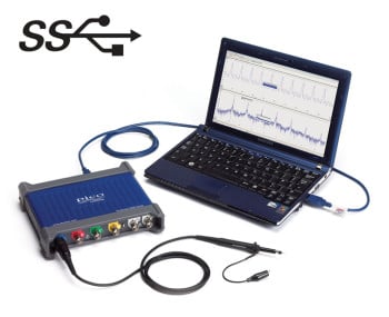
USB 3.0 PC oscilloscope

USB connectivity

The USB connection not only allows high-speed data acquisition and transfer, but also makes printing, copying, saving, and emailing your data from the field quick and easy. USB powering removes the need to carry around a bulky external power supply, making the kit even more portable for the engineer on the move.

PicoScope 3000 Series oscilloscopes feature a SuperSpeed USB 3.0 connection, making the already-optimized process of data transfer and waveform update rates even faster. Further benefits of a USB 3.0 connection include faster saving of waveforms and faster gap-free continuous streaming of up to 125 MS/s when using the SDK, while the scope is still backward-compatible with older USB systems.

ZAR 200023,0000

PicoLog 1000 Series

sku Product SKU:  PIC-LOG1000-S

A DISTINGUISHED PEDIGREE

The PicoLog 1000 Series is the result of a distinguished lineage that goes back to the release of our first multichannel data logger — the ADC-11 — in 1993. The original ADC-11, and its successor the USB ADC-11, proved to be the perfect choice for users wanting a low–cost way to measure and record multiple signals. The PicoLog 1000 Series builds on this success to give you the same low-cost data acquisition but with greater power and performance. (Because the ADC-11 was so popular we’ve also added a USB ADC-11 compatibility mode which allows you to use your PicoLog 1000 logger as a direct replacement to the USB ADC-11.)

Data logger terminal board

AN EXPANDABLE MULTICHANNEL DATA ACQUISITION SYSTEM

The budget model PicoLog 1012 has 12 input channels and 10 bit resolution. The powerful PicoLog 1216 has 16 channels and 12 bit resolution. Need more channels? No problem. Using PicoLog you can connect up to 4 Pico data loggers to one PC — giving you a potential 64 channel PicoLog 1000 Series data acquisition system, or the ability to use your PicoLog 1000 logger with other devices such as the USB TC-08 Thermocouple Data Logger.

OPTIONAL TERMINAL BOARD

The optional terminal board has screw terminals to allow sensor wires to be attached to the data logger without soldering. The terminal board also has locations where you can fit resistors to offset and extend the input ranges of the logger.

16 channel picoscope

FAST AND ACCURATE

With 10 or 12-bit resolution and multiple sampling modes, a PicoLog 1000 Series logger will meet your data logging needs. The PicoLog 1000 Series has 3 sampling modes: Streaming mode allows channel voltage readings to be logged continuously at up to 100 kS/s, while block mode captures up to the full 1 MS/s  sample rate of the logger for a duration limited by the 8000 sample buffer, both these speeds applying to single-channel operation. The PicoLog application provides an extra mode, real-time continuous sampling, which provides averaged, time-accurate readings with automatic measurements at up to 1 kS/s on any number of channels.

ZAR 3982,0000

UNIT1

PicoScope 9404A-25

sku Product SKU:  PIC-9404A-25

The highest bandwidth SXRTO yet

The PicoScope 9404A-25 SXRTO (Sampler-Extended Real-Time Oscilloscope) extends the bandwidth of the PicoScope 9400 Series with a 25 GHz model. It combines the benefits of real-time and equivalent-time sampling to create a truly incredible oscilloscope capable of capturing signals up to 25 GHz.

Packed with features

Packed with features

The PicoScope 9404A-25's random sampling is ideal for measuring high speed interfaces with repetitive signals or clock streams. It can record high-speed signals such as gigabit digital systems on up to four channels at once. The PicoScope 9404A Series is invaluable for the design, testing, servicing and manufacturing of telecoms equipment. With these applications in mind, the free PicoSample 4 software is packed with useful measurements and features. Draw eye diagrams with ease and analyze them with one of over 175 built-in masks (or create your own). Plot trends in your data such as pulse width or period over time. 


Control of the PicoScope 9404A-25 can also be automated, including a remote control option via over USB or LAN using ActiveX control. 

Fast setup for fast signals

Fast setup for fast signals

The PicoScope 9404A-25 has a 25 GHz front-end, an effective sampling rate up to 5 TS/s and a maximum time resolution of 10 ps/div. The external prescaled trigger is able to work up to 20 GHz, direct trigger to 2.5 GHz and clock recovery is also available for up to an impressive 11.3 Gb/s. A direct trigger means there's no need for an external clock or trigger source - simply connect the scope to the circuit you want to measure.


Unlike many real-time oscilloscopes, the PicoScope 9404A-25 maintains its 12-bit resolution throughout its bandwidth, no matter how many channels are enabled.

What is a PicoScope SXRTO?

Real-Time Oscilloscopes (RTOs) - capture any signal

A real-time oscilloscope has a free-running ADC. They use digital triggers to record when the signal exceeds a threshold and therefore align the signals in time. RTOs rely on oversampling - the sample rate must be much higher than the maximum signal frequency. To generate an accurate view of the signal, many scopes will sample at three or even five times their maximum input bandwidth. 

Sampling oscilloscopes - see repetitive signals far beyond Nyquist

A sampling oscilloscope relies on repeated signals. They only capture a single sample per trigger event and this sample is at least 40 ns after the trigger event itself. The individual samples from multiple trigger events are then recombined to build up a picture of the overall signal. 

A sampling scope cannot trigger directly on the signal itself and instead needs a separate trigger signal from an external source. Sampling scopes rely on accurate triggering to overlay the repeated signals so that even with a sampling rate significantly below the signal frequency, they can display an accurate version of the overall signal.

Sampler-Extended Real-Time Oscilloscopes combine both approaches

A PicoScope SXRTO triggers on the input signal, like an RTO. However, unlike most RTOs it uses an analog triggering circuit separate to the main signal path to determine when the trigger happens. Using this type of analog triggering is much more accurate than the digital trigger of an RTO. 

The result is a free-running ADC that is able to capture and store information before and after the trigger point, but with the huge bandwidth capabilities of a sampling oscilloscope. 

PicoScope 9404A-25 inputs, outputs and indicators

Front panel

Rear panel

The front panel of the oscilloscope brings together the power indicator, the four 25 GHz 50 Ω channel inputs and the trigger inputs and outputs. 


The power/status/trigger LED is green under normal operation but is also used to indicate connection progress and trigger. You can enable any number of the 4 input channels without affecting the 25 GHz sampling rate; only the capture memory (250 kS) is shared between the enabled channels.


The external direct trigger input supports up to 5 GHz and is positioned alongside the 20 GHz prescale trigger input. The trigger output connection can be used to synchronize an external device to the PicoScope 9404A’s rising edge, falling edge and end of holdoff triggers.

Key features of the PicoScope 9400 Series

The PicoScope 9400A Series is a range of Sampler-Extended Real-Time Oscilloscopes (SXRTO) available with up to 25 GHz bandwidth, ideal for capturing step transitions down to 14 ps and impulses down to 28 ps. The  maximum sample rate is 5 TS/s using random sampling, which equates to a timing resolution of 0.2 ps. The use of random sampling means an SXRTO can capture pre-trigger information and does not require a separate clock input. As such, the hardware includes a built-in trigger circuit on every channel, up to 5 GHz when using divide mode. An external direct clock input can trigger on signals up to 5 GHz, while the prescaled input accepts signals up to 20 GHz. The jitter from this direct trigger is as low as 1.5 ps. In terms of vertical resolution, the wide ±800 mV full-scale input range is augmented by 10 mV/div to 250 mV/div digital gain ranges on up to four channels. An optional clock recovery circuit can output a recovered clock and data up to 11.3 Gb/s. 


The touchscreen-compatible PicoSample 4 software is packed with features to assist with the characterizing of everything from signals (eye diagrams, pulse/impulse characterization) to digital systems and even semiconductors. It comes pre-loaded with over 175 mask tests for common protocols including Ethernet, HDMI 1, PCIe, SATA and USB 2.0. The scope can store traces up to 250 kS long, shared between all active channels. The buffer memory is available on any of the three acquisition modes - real-time, random and roll. Four independent zoom channels let you closely inspect your data, with resolution down to 0.4 ps. Using your PC's monitor rather than a built in screen means those zoom views can be enlarged as much as you need to see all the detail. You can also personalize the display by hiding menus and controls and adjusting the colors to suit your needs. All of the PicoSample features are included in the price, with no additional hidden costs.

Measure fast pulses with an SXRTO

A customer wanted to measure a fast laser pulse with a rise time of less than 50 ps and a pulse width of less than 200 ps. They used a PicoScope SXRTO to see exactly what they needed.

To measure the output of the laser it was connected to a PicoScope 9400 Series oscilloscope via an optical-electrical adaptor. As the scope can trigger directly off the signal input the customer didn't need to use any extra external components. 

The PicoScope 9404A-25 has a rise time of 14 ps and so the shape seen on the screen is due to the laser pulse and is not influenced by the measurement setup. The PicoScope 9404A-25 can also capture pulses down to 28 ps so even shorter pulses could be measured accurately.

Every detail in the laser's pulse response is easy to see because the vertical resolution is 12 bits, even at the highest frequencies. Some real-time oscilloscopes will limit their resolution at higher frequencies. This might be because of limitations of the analog-to-digital hardware or because of data bandwidth limitations. Because the PicoScope 9404A samples at a maximum of 500 MS/s neither the timebase nor the number of active channels restricts the resolution.

Why should you choose an SXRTO?

Digital system design

With over 175 built-in masks covering protocols such as Ethernet, HDMI and USB, you can make sure your system design is correct from the start.

Timing and phase analysis

Locate the source of timing errors with confidence: the PicoScope 9400A has jitter less than 1.5 ps. Use histograms to precisely characterize jitter.

Telecom and radar testing

Check signal, pulse and impulse integrity of RF systems up to 25 GHz. Be confident your system meets standards before expensive compliance testing.

Service and manufacturing

With quicker and simpler setup than a standard sampling oscilloscope, an SXRTO is perfectly suited to a service environment. Save and recall setup files for common tests and reduce the time taken to repair equipment.

Clock and data recovery

Clock and data recovery (CDR) is available as a factory-fit optional trigger feature on the PicoScope 9404A-25.

Associated with high-speed serial data applications, clock and data recovery will already be familiar to PicoScope 9300 users. While low-speed serial data can often be accompanied by its clock as a separate signal, at high speed this approach would accumulate timing skew and jitter between the clock and the data that could prevent accurate data decode. Thus high-speed data receivers will generate a new clock, and using a phase-locked loop (PLL) technique they will lock and align that new clock to the incoming data stream. This is the recovered clock and it can be used to decode and thus recover data accurately. We have also saved the cost of an entire clock signal path by now needing only the serial data signal.

When fitted, the PicoScope 9400 CDR option can be selected as the trigger source from any input channel. Additionally, for use by other instruments or by downstream system elements, two SMA(f) outputs present recovered clock and recovered data on the rear panel.

In many applications where our oscilloscopes are used to view data, the data generator and its clock are typically nearby, allowing us to trigger directly from that clock. However, if only the data is accessible—such as at the far end of an optical fiber—we will need the CDR option to recover the clock and use it as the trigger source instead. The CDR option may also be necessary for demanding eye and jitter measurements to ensure our instrument assesses signal quality as accurately as a recovered clock and data receiver would.

Request for clock recovery

What's in the box

Description Quantity
PicoScope 9400 Series sampler-extended real-time oscilloscope (SXRTO) 1
PicoSample 4 software supplied on USB stick 1
Quick start guide 1
12 V power supply, IEC inlet 1
Localized IEC mains leads (US, UK, AUS, EU) 4
USB cable, 1.8 m 1
PicoWrench N / SMA / PC3.5 / K combination wrench 1
Storage / carry case 1
LAN cable, 1 m 1

ZAR 644649,0000