Online Buying Store Product Details

{{image.AltTag}} {{image.AltTag}}
Default Image Default Image

{{details.product.ModelName}}

Sku: {{details.product.ModelNumber}}

Price: {{(details.product.BundleUnitCost || details.product.UnitCost) | currency : 'R' : 2}} (Excl. VAT)

Now: {{(details.product.BundleSalePrice || details.product.SalePrice) | currency : 'R' : 2}} (Excl. VAT)


OUT OF STOCK, Contact office for lead time
Delivery time for this product is 5-7 business days
{{details.product.PriceUnits}}
Please fill out this field...
Please enter a number...
Please enter at least 1...
Please enter at max 999999...

You purchased this item on {{details.product.OrderHistory[0].OrderDate | date : 'yyyy-MM-dd'}}

Personal Greeting

Sampling Oscilloscopes to 30 GHz with TDR/TDT and optical models

Sampling Oscilloscopes to 30 GHz with TDR/TDT and optical models

20 to 30 GHz electrical, 9.5 GHz optical, TDR/TDT, 2-channel and 4-channel, compact, portable, USB instruments.
These units occupy very little space on your workbench and are small enough to carry with your laptop for on-site testing, but that’s not all. Instead of using remote probe heads attached to a large benchtop unit, you can position the scope right next to the device under test. Now all that lies between your scope and the DUT is a short, low-loss coaxial cable. Everything you need is built into the oscilloscope, with no expensive hardware or software add-ons to worry about.

Key specifications

  • 15 TS/s (64 fs) sequential sampling, display resolution to 640 TS/s (1.5 fs)
  • Up to 15 GHz prescaled, 2.5 GHz direct trigger, and 11.3 Gb/s clock recovery
  • Industry-leading 16-bit 1 MS/s ADC and 60 dB dynamic range
  • Eye and mask testing to 20 Gb/s with up to 223–1 pattern lock
  • Intuitive, touch-compatible Windows user interface
  • Comprehensive built-in measurements, histogramming, and editable data mask library
  • Integrated, differential, deskewable TDR/TDT step generator

Typical applications

  • Telecom and radar test, service and manufacturing
  • Optical fibre, transceiver and laser testing
  • RF, microwave and gigabit digital system measurements
  • Radar bands I, G, P, L, S, C, X, Ku
  • Precision timing and phase analysis
  • Digital system design and characterisation
  • Eye diagram, mask and limits test to 10 Gb/s
  • Ethernet, HDMI 1, HDMI 2, PCI, SATA, USB 2.0, USB 3.0
  • TDR/TDT analysis of cables, connectors, backplanes, PCBs and networks
  • Optical fibre, transceiver and laser test
  • Semiconductor characterisation

Remember: the price you pay for your PicoScope Sampling Oscilloscope is the price you pay for everything – we don’t charge you for software features or updates.

High-bandwidth probes

The PicoConnect 900 Series low-impedance, high-bandwidth probes are ideal companions for the PicoScope 9400 Series, allowing cost-effective fingertip browsing of fast signals. Two series are available:

  • RF, microwave and pulse probes for broadband signals up to 5 GHz (10 Gb/s)
  • Gigabit probes for data streams such as USB 2, HDMI 1, Ethernet, PCIe and SATA

30 GHz bandwidth in a compact USB instrument

30 GHz bandwidth in a compact USB instrument

PicoScope 9300 Series sampling oscilloscopes use triggered sequential sampling to capture high-bandwidth repetitive or clock-derived signals without the expense or jitter of a very high-speed clocked sampling system such as a real-time oscilloscope. 30 GHz bandwidth allows measurement of 14 ps transitions, and low sampling jitter enables timing resolution down to 0.064 ps. Sequential sampling rate of 1 MS/s, unsurpassed by other sampling oscilloscopes, enables rapid building of waveforms, eye diagrams and histograms.

These two and four channel units occupy very little space on a workbench and are small enough to carry with a laptop for on-site testing. Furthermore, instead of using remote probe heads attached to a large bench-top unit, you can position the PicoScope 9300 right next to the device under test and connect to it with short, low-loss coaxial cables.

Everything you need is built into the oscilloscope, with no expensive hardware or software add-ons to worry about. Alternatively, you can use your PicoScope 9300 with a stand-alone PG900 TDR/TDT differential fast pulse generator to gain the extra versatility and configurability of independent high-performance source and measurement instruments.

Trigger modes

2.5 GHz direct and up to 18 GHz prescaled trigger

Sampling oscilloscopes accept their trigger from a separate input, either directly for repetition rates up to 2.5 GHz or via a prescaling divider input, for repetition rates up to 18 GHz (14 GHz on 20 GHz models).

Built-in 11.3 Gb/s clock data recovery trigger

To support serial data applications in which the data clock is not available as a trigger, or for which trigger jitter needs to be reduced, the PicoScope 9302 and 9321 include a clock recovery module. This continuously regenerates the data clock from the incoming serial data or trigger signal and can do so with reduced jitter even over very long trigger delays or for pattern lock applications. A divider accessory kit is included to route the signal to both the clock recovery and oscilloscope inputs.

9.5 GHz optical model

The PicoScope 9321-20 includes a built-in precision optical-to-electrical converter. With the converter output routed to one of the scope inputs (optionally through an SMA pulse shaping filter), the PicoScope 9321-20 can analyse standard optical communications signals such as OC48/STM16, 4.250 Gb/s Fibre Channel and 2xGB Ethernet. The scope can perform eye-diagram measurements with automatic measurement of optical parameters including extinction ratio, S/N ratio, eye height and eye width. With its integrated clock recovery module, the scope is usable to 11.3 Gb/s.

The converter input accepts both single-mode (SM) and multi-mode (MM) fibres and has a wavelength range of 750 to 1650 nm.

TDR/TDT analysis

The PicoScope 9311 oscilloscopes feature built-in step generators for time-domain reflectometry and transmission measurements. The 9311‑20 features deskewable rising and falling step generators suited to single-ended and differential measurements. These features can be used to characterise transmission lines, printed circuit traces, connectors, and cables with 16 mm resolution for impedance measurements and 4 mm resolution for fault detection.

tdr connections

The PicoScope 9311-20 generates 2.5 to 7 V steps with 60 ps rise time from built-in step recovery diodes. It is supplied with a comprehensive set of calibrated accessories to support your TDR/TDT measurements, including cables, signal dividers, adaptors, attenuator, and reference load and short.

The PicoScope 9311-20 TDR/TDT model includes source deskew with 1 ps resolution and comprehensive calibration, reference plane, and measurement functions. Voltage, impedance, or reflection coefficient (ρ) can be plotted against time or distance.

An alternative approach to TDR/TDT capability is to pair any 9300 Series scope with a stand-alone PG900 pulse generator. These instruments include similar differential step recovery diode step generators and also offer an option of 40 ps tunnel diode step generation. This brings extra flexibility and the ability to remotely position the pulse source. The generators also enable TDT and TDR with the PicoScope 9301, 9302 clock recovery, 9321 optical, and 9341 4-channel sampling oscilloscopes.

Built-in signal generator

All the PicoScope 9300 Series scopes can generate industry-standard and custom signals including clock, pulse and pseudo-random binary sequence. You can use these to test the instrument’s inputs, experiment with its features and verify complex setups such as mask tests. AUX OUTPUT can also be configured as a trigger output.

PicoConnect® 900 Series: the shape of probes to come

The PicoConnect 900 Series is a range of low-invasive, high-frequency passive probes, designed for microwave and gigabit applications up to 9 GHz and 18 Gb/s. They deliver unprecedented performance and flexibility at a low price and are an obvious choice to use alongside the PicoScope 9300 Series scopes.

Features of the PicoConnect 900 Series probes:

  • Extremely low loading capacitance of < 0.3 pF typical, 0.4 pF upper test limit for all models
  • Slim, fingertip design for accurate and steady probing or solder-in at fine scale
  • Interchangeable SMA probe heads at division ratios of 5:1, 10:1 and 20:1, AC or DC coupled
  • Accurate probing of high-speed transmission lines for Z0 = 0 Ω to 100 Ω
  • Class-leading uncorrected pulse/eye response and pulse/eye disturbance

PicoSource® PG900 Series differential pulse generators

For greater versatility than a built-in signal generator can offer, you may want to separate your high-performance fast-step TDR/TDT pulse source from the sampling oscilloscope and have two instruments to use either stand-alone or together as required.

The PicoSource PG900 Series generators contain the same step recovery diode pulse source as the PicoScope 9311, or slightly faster but reduced amplitude tunnel diode pulse heads, rehoused in a separate USB-controlled instrument. All are supplied with PicoSource PG900 control software.

Bessel-Thomson filter for optical waveshape analysis

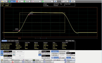
SMA Bessel-Thomson pulse-shaping filters

For use with the 9321-20 optical-to-electrical converter, a range of Bessel–Thomson filters is available for standard bit rates. These filters are essential for accurate characterisation of signals emerging from an optical transmission system.

The first diagram, shows the ringing typical of an unequalized O/E converter output at 622 Mb/s. The second diagram, shows result of connecting 622 Mb/s B-T filter

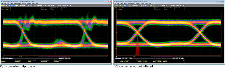
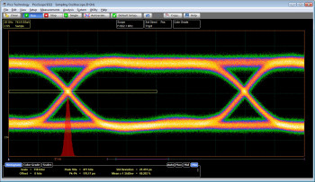
The first diagram shows the ringing typical of an unequalised O/E converter output at 622 Mb/s. The second diagram shows the result of connecting a 622 Mb/s B-T filter.

The first eye diagram, above left, shows the ringing typical of an unequalised O/E converter output at 622 Mb/s. The second eye diagram, above right, shows the result of connecting the 622 Mb/s B-T filter. This is an accurate representation of the signal that an equalised optical receiver would see, enabling the PicoScope 9321 to display correct measurements.

Application-configurable PicoSample 3 oscilloscope software

The PicoSample 3 workspace takes full advantage of your available display size and resolution.

Designed for ease of use

The PicoSample 3 workspace takes full advantage of your available display size and resolution. You decide how much space to give to the trace display and the measurements display, and whether to open or hide the control menus. The user interface is fully touch- or mouse-operable, with grabbing and dragging of traces, cursors, regions and parameters. There are enlarged parameter controls for use on smaller touch displays. To zoom, either draw a zoom window or use the more traditional dual timebase, delay and scaling controls.

A choice of screen formats

When working with multiple traces, you can display them all on one grid or separate them into two or four grids. You can also plot signals in XY mode with or without additional voltage-time grids. The persistence display modes use colour-coding or shading to show statistical variations in the signal. Trace display can be in either dots-only or vector format.

Eye-diagram analysis

The PicoScope 9300 Series scopes quickly measure more than 30 fundamental parameters used to characterise non-return-to-zero (NRZ) signals and return-to-zero (RZ) signals. Up to ten parameters can be measured simultaneously, with comprehensive statistics also shown.

The measurement points and levels used to generate each parameter can optionally be drawn on the trace.

Eye-diagram analysis can be made even more powerful with the addition of mask testing, as described below.

Pattern sync trigger and eye line mode

When a repeating data pattern such as a pseudorandom bit sequence is present, an internal trigger divider can lock to it. You can then use eye-line mode to move the trigger point, and view point, along the whole pattern, bit by bit. Eye-line scan mode is also available to build an eye diagram from a user-selected range of bit intervals through to the whole pattern. These features are useful for analysing data-dependent waveshapes.

Mask testing

PicoSample 3 has a built-in library of over 160 masks for testing data eyes. It can count or capture mask hits or route them to an alarm or acquisition control. You can stress-test against a mask using a specified margin, and locally compile or edit masks.

There’s a choice of grey-scale and colour-graded display modes to aid in analysing noise and jitter in eye diagrams. There is also a statistical display showing a failure count for both the original mask and the margin.

The extensive menu of built-in test waveforms is invaluable for checking your mask test setup before using it on live signals.

Measurement of over 100 waveform parameters with statistics

The PicoScope 9300 Series scopes quickly measure well over 100 standard waveform and eye parameters, either for the whole waveform or constrained between markers. The markers can also make on-screen ruler measurements, so you don’t need to count graticules or estimate the waveform’s position. Up to ten simultaneous measurements are possible. The measurements conform to IEEE standard definitions, but you can edit them for non-standard thresholds and reference levels using the advanced menu or by dragging the on-screen thresholds and levels. You can apply limit tests to up to four measured parameters.

A dedicated frequency counter shows signal frequency at all times, regardless of measurement and timebase settings.

Waveform mathematics menu

Powerful mathematical analysis

The PicoScope 9300 Series scopes support up to four simultaneous mathematical combinations or functional transformations of acquired waveforms.

You can select any of the mathematical functions to operate on either one or two sources. All functions can operate on live waveforms, waveform memories or even other functions. There is also a comprehensive equation editor for creating custom functions of any combination of source waveforms.

Waveform mathematics

Choose from 61 maths functions, or create your own

  • Add, Subtract, Multiply, Divide, Invert, Absolute, Exponent, Logarithm, Differentiate, Integrate, Inverse, FFT, Interpolation, Smoothing

picosample-fft-analysis

FFT analysis

All PicoScope 9300 Series oscilloscopes can calculate real, imaginary and complex Fast Fourier Transforms of input signals using a range of windowing functions. The results can be further processed using the maths functions. FFTs are useful for finding crosstalk and distortion problems, adjusting filter circuits designed to filter out certain harmonics in a waveform, testing impulse responses of systems, and identifying and locating noise and interference sources.

Histogram analysis

Behind the powerful measurement and display capabilities of the 9300 Series lies a fast, efficient data histogramming capability. A powerful visualisation and analysis tool in its own right, the histogram is a probability graph that shows the distribution of acquired data from a source within a user-definable window.

Histograms can be constructed on waveforms on either the vertical or horizontal axes. The most common use for a vertical histogram is measuring and characterising noise and pulse parameters. A horizontal histogram is typically used to measure and characterise jitter.

Software Development Kit

The PicoSample 3 software can operate as a stand-alone oscilloscope programme or under ActiveX remote control. The ActiveX control conforms to the Windows COM interface standard so that you can embed it in your own software. Unlike more complex driver-based programming methods, ActiveX commands are text strings that are easy to create in any programming environment. Programming examples are provided in Visual Basic (VB.NET), MATLAB, LabVIEW and Delphi, but you can use any programming language or standard that supports the COM interface, including JavaScript and C. National Instruments LabVIEW drivers are also available. All the functions of the PicoScope 9300 and the PicoSample software are accessible remotely.


PicoScope 9300 manuals

Resource Language Version Size Updated
Data Sheets:
PicoScope 9300 Series Data Sheet English 20 6 MB November 10 2023
PicoScope 9300 系列 数据表 中文 (简体) 1 6 MB December 20 2023
PicoScope 9300 シリーズデータシート 日本語 1 6 MB December 20 2023
PicoScope 9300 시리즈 데이터 시트를 한국어 1 6 MB December 20 2023
User’s Guides:
PicoScope 9300 Series User’s Guide English 14 30 MB May 30 2023
Programmer’s Guides:
PicoScope 9300 Series Programmer’s Guide English 4 1 MB March 07 2017
Quick Start Guides:
PicoScope 9000 Series Quick Start Guide English 15 2 MB October 04 2022
Catalogues:
PicoScope 9300 시리즈 데이터 시트를 한국어 1 6 MB December 20 2023
Application Notes:
The Trouble with Oscilloscope Probes and an “off-piste” design for microwave and gigabit application English 2 2 MB March 16 2017
PicoScope 9000 Series Questions and Answers English 2 356 KB August 05 2015
Technical Data:
PicoScope 9000 calibration certificate example English 1 1 MB September 05 2017
Declarations:
PicoScope 9300 Series Statement of Volatility English 1 71 KB March 31 2017
PicoScope 9301 Series UKCA Declaration of Conformity English 1 258 KB December 22 2022
PicoScope 9321 and 9302 Series UKCA Declaration of Conformity English 1 273 KB December 22 2022
PicoScope 9311 Series UKCA Declaration of Conformity English 1 255 KB December 22 2022
PicoScope 9341 Series UKCA Declaration of Conformity English 1 252 KB December 22 2022


Fore more infomation click here