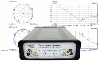
PicoVNA 106 features

‘Quad RX’ four-receiver architecture
In a VNA a swept sine-wave signal source is used to sequentially stimulate the ports of the interconnect or device under test. The amplitude and phase of the resultant transmitted and reflected signals appearing at both VNA ports are then received and measured. To wholly characterize a 2-port device under test (DUT), six pairs of measurements need to be made: the amplitude and phase of the signal that was emitted from both ports, and the amplitude and phase of the signal that was received at both ports for each source. In practice this can be achieved with a reasonable degree of accuracy with a single source, a transfer switch and two receivers; the latter inputs being switched through a further pair of transfer switches. Alternatively three receivers can be used with an additional input transfer switch or, as in the PicoVNA, four receivers can be used. Using four receivers eliminates the receiver input transfer switch errors (chiefly leakage and crosstalk) that cannot be corrected. These residual errors are always present in two- and three-receiver architectures and lead to lower accuracy than that of the Quad RX design.
Support for 8 and 12-term calibration and the unknown thru
Almost all vector network analyzers are calibrated for twelve error sources (six for each signal direction). This is the so-called 12-term calibration, which experienced VNA users are used to performing fairly regularly. In a four-receiver design some error sources are so reduced that 8-term calibration becomes possible, along with an important and efficient calibration technique known as the unknown thru. This gives the ability to use any thru interconnect (including the DUT) during the calibration process, vastly simplifying the procedure and reducing the number of costly calibration standards that need to be maintained.
Advanced vector network analyser users will be pleased to know that internal a-wave and b-wave data is made available for export under a diagnostic facility. Amongst others, Transfer switch error terms can therefore be derived.

Bias-Ts
Bias-Ts are often not provided, or available as costly extras, on other VNAs. Use the PicoVNA 106’s built-in bias-Ts to provide a DC bias or test stimulus to active devices without the complexity and cost of external DC-blocks. The bias is supplied from external power supplies or test sources routed to the SMB connectors adjacent to each VNA port.

Test cables and calibration standards
A range of RF and Microwave accessories are available from Pico Technology. Test cables and calibration standards have particular significance to the overall performance of a VNA, so we recommend that you select your accessories carefully. Cables and standards are often the weakest links in a VNA measurement, generally contributing significantly to measurement uncertainty despite their high cost. At the lowest levels of uncertainty, costs can be significant and measurements can be compromised by seemingly quite minor damage or wear. For these reasons, many customers hold both premium-grade items for calibration, reference or measurement standards, and standard-grade items as working or transfer standards and cables. Pico Technology can now offer cost-effective solutions in both grades.

Phase- and amplitude-stable test leads
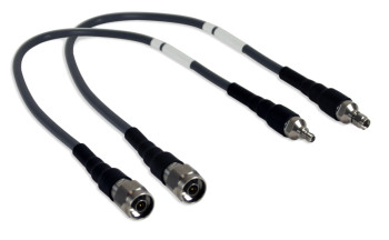
Two test cable types and grades are recommended and provided by Pico Technology. Both of high quality, with robust and flexible construction and stainless steel connectors, the main difference between them is the stability of their propagation velocity and loss characteristic when flexed; that is, the degree to which a measurement could change when the cables are moved or formed to a new position. Cables are specified in terms of flatness and phase variation at up to 6 GHz when a straight cable is formed as one 360° turn around a 10 cm mandrel.