Poor grounding increases the risk of equipment failure; it is dangerous. Facilities need to have adequately grounded electrical systems so that in the event of a lightning strike, or utility overvoltage, current will find a safe path to earth.
There are four types of earth ground testing methods available:
- Soil Resistivity (using stakes)
- Fall-of-Potential (using stakes)
- Selective (using one clamp and stakes)
- Stakeless (using two clamps only)
Soil resistivity measurement
Why determine the soil resistivity?
Soil resistivity is most necessary when determining the design of the grounding system for new installations (green field applications) to meet your ground resistance requirements. Ideally, you would find a location with the lowest possible resistance. But as discussed before, more elaborate grounding systems can overcome poor soil conditions.
The soil composition, moisture content, and temperature impact soil resistivity. Soil is rarely homogenous, and the resistivity of the soil will vary geographically and at different soil depths. Moisture content changes seasonally and varies according to the nature of the sub-layers of the earth and the depth of the permanent water table. Since soil and water are generally more stable at deeper strata, it is recommended that the ground rods be placed as deep as possible into the earth, at the water table, if possible. Also, ground rods should be installed where there is a stable temperature, i.e. below the frost line. For a grounding system to be effective, it should be designed to withstand the worst possible conditions.
How do I calculate soil resistivity?
The measuring procedure described below uses the universally accepted Wenner method developed by Dr. Frank Wenner of the US Bureau of Standards in 1915. (F. Wenner, A Method of Measuring Earth Resistivity; Bull, National Bureau of Standards, Bull 12(4) 258, p. 478-496; 1915/16.)
The formula is as follows:
ρ = 2p A R
(ρ = the average soil resistivity to depth A in ohm—cm)
p = 3.1416
A = the distance between the electrodes in cm
R = the measured resistance value in ohms from the test instrument
Note: Divide ohm—centimetres by 100 to convert to ohm—meters. Just watch your units.
Example: You have decided to install three-meter-long ground rods as part of your grounding system. To measure the soil resistivity at a depth of three meters, we discussed a spacing between the test electrodes of three meters.
To measure the soil resistivity starts the Fluke 1625 and read the resistance value in ohms. In this case, assume the resistance reading is 100 ohms. So, in this case, we know:
A = 3 meters, and
R = 100 ohms
Then the soil resistivity would equal:
ρ= 2 x p x A x R
ρ = 2 x 3.1416 x 3 meters x 100 ohms
ρ = 1885 Ωm
How do I measure soil resistance?
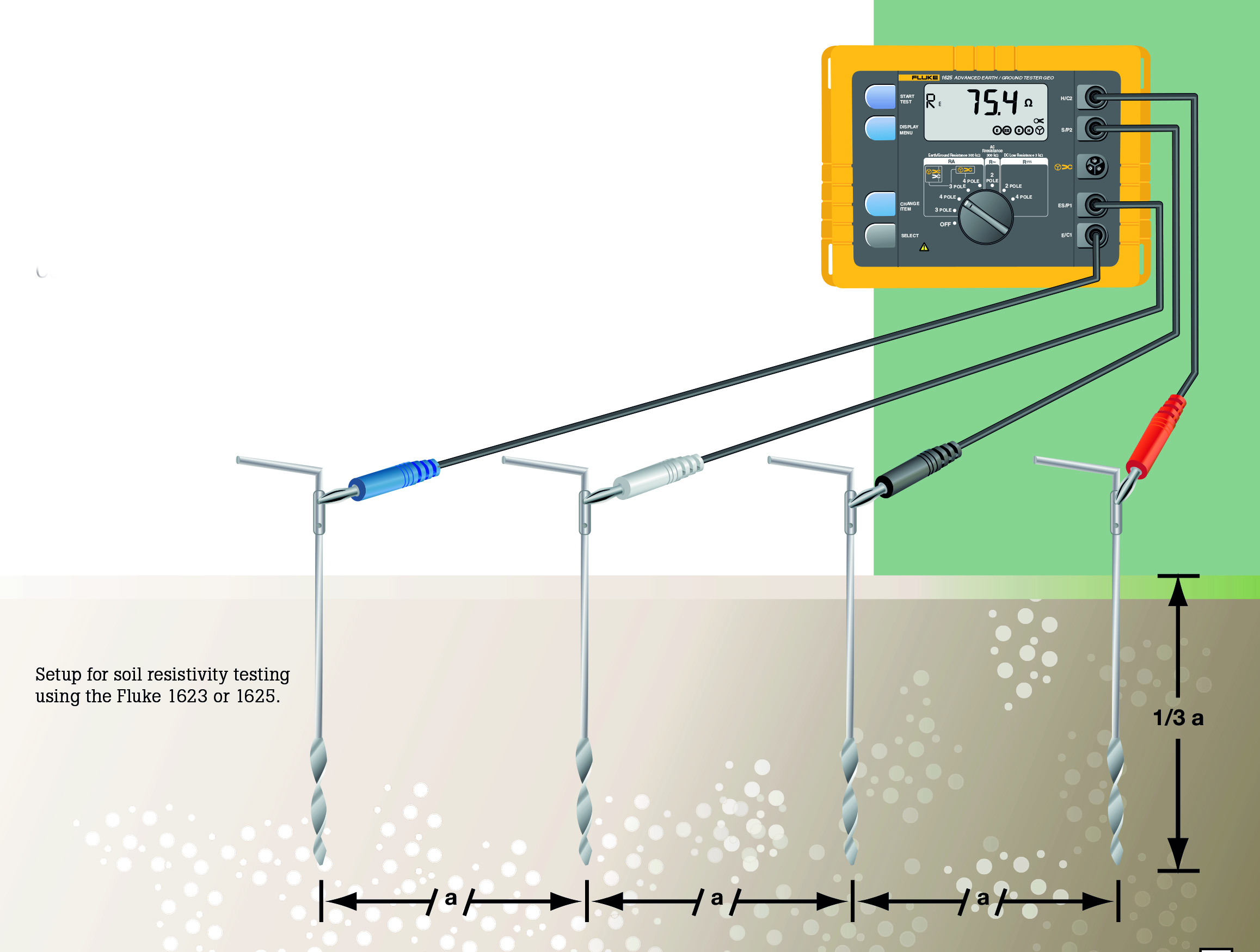
To test soil resistivity, connect the ground tester as shown below.
As you can see, four earth ground stakes are positioned in the soil in a straight line, equidistant from one another. The distance between earth ground stakes should be at least three times greater than the stake depth. So if the depth of each ground stake is one foot (.30 meters), ensure the distance between stakes is greater than three feet (.91 meters). The Fluke 1625 generates a known current through the two outer ground stakes, and the drop in voltage potential is measured between the two inner ground stakes. Using Ohm’s Law (V=IR), the Fluke tester automatically calculates the soil resistance.
Because measurement results are often distorted and invalidated by underground pieces of metal, underground aquifers, etc., additional measurements where the stake’s axis is turned 90 degrees are always recommended. Changing the depth and distance several times produces a profile that can determine a suitable ground resistance system.
Soil resistivity measurements are often corrupted by the existence of ground currents and their harmonics. The Fluke 1625 uses an Automatic Frequency Control (AFC) System to prevent this from occurring. This automatically selects the testing frequency with the least amount of noise, enabling you to get a precise reading.
Fall-of-Potential measurement
The Fall-of-Potential test method is used to measure the ability of an earth ground system or an individual electrode to dissipate energy from a site.
How does the Fall-of-Potential test work?
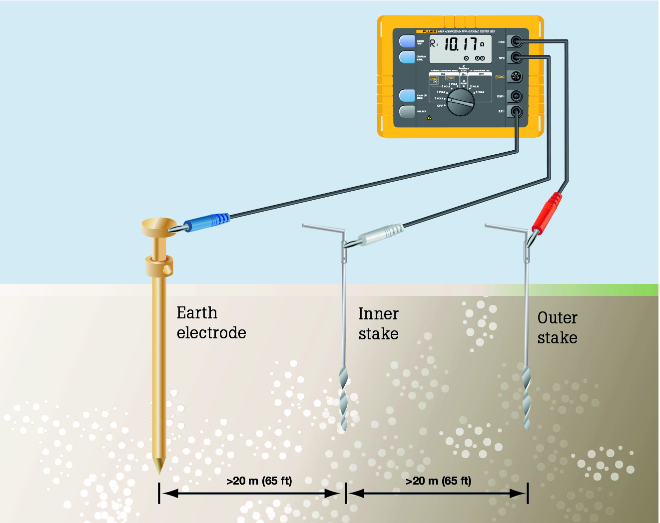
First, the earth electrode of interest must be disconnected from its connection to the site. Second, the tester is connected to the earth electrode. Then, for the 3-pole Fall-of-Potential test, two earth stakes are placed in the soil in a direct line—away from the earth electrode. Usually, a spacing of 20 meters (65 feet) is sufficient. For more detail on placing the stakes, see the next section.
A known current is generated by the Fluke 1625 between the outer stake (auxiliary earth stake) and the earth electrode, while the drop in voltage potential is measured between the inner earth stake and the earth electrode. Using Ohm’s Law (V = IR), the tester automatically calculates the resistance of the earth electrode.
Connect the ground tester as shown in the picture. Press START and read out the RE (resistance) value. This is the actual value of the ground electrode under test. If this ground electrode is in parallel or series with other ground rods, the RE value is the total value of all resistances.
How do you place the stakes?
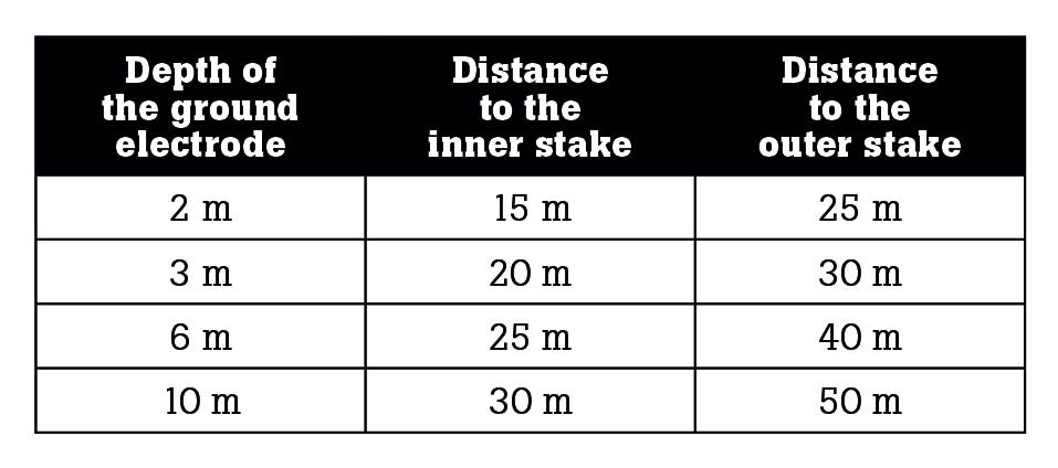
To achieve the highest degree of accuracy when performing a 3–pole ground resistance test, it is essential that the probe is placed outside the sphere of influence of the ground electrode under test and the auxiliary earth.
If you do not get outside the sphere of influence, the effective areas of resistance will overlap and invalidate any measurements you take. The table is a guide for appropriately setting the probe (inner stake) and auxiliary ground (outer stake).
To test the results’ accuracy and ensure that the ground stakes are outside the spheres of influence, reposition the inner stake (probe) 1 meter in either direction and take a new measurement. Suppose there is a significant change in the reading (30 %). In that case, you need to increase the distance between the ground rod under test, the inner stake (probe) and the outer stake (auxiliary ground) until the measured values remain relatively constant when repositioning the internal stake (probe).
Selective measurement

Selective testing is very similar to the Fall- of-Potential testing, providing all the same measurements but in a much safer and easier way. With Selective testing, the earth electrode of interest does not need to be disconnected from its connection to the site! The technician does not have to endanger himself by disconnecting ground, nor endanger other personnel or electrical equipment inside a non-grounded structure.
As with the Fall-of-Potential test, two earth stakes are placed directly away from the earth electrode in the soil. Typically, a spacing of 20 meters is sufficient. The tester is then connected to the earth electrode of interest, with the advantage that the connection to the site doesn’t need to be disconnected. Instead, a special clamp is placed around the earth electrode, eliminating the effects of parallel resistances in a grounded system, so only the earth electrode of interest is measured.
As before, a known current is generated by the Fluke 1625 between the outer stake (auxiliary earth stake) and the earth electrode, while the drop in voltage potential is measured between the inner earth stake and the earth electrode. Only the current flowing through the earth electrode of interest is measured using the clamp. The generated current will also flow through other parallel resistances, but only the current through the clamp (i.e. the current through the earth electrode of interest) is used to calculate resistance (V=IR).
If the total resistance of the ground system should be measured, then each earth electrode resistance must be measured by placing the clamp around each individual earth electrode. Then the total resistance of the ground system can be determined by calculation.
Testing individual ground electrode resistances of high-voltage transmission towers with the overhead ground or static wire requires that these wires be disconnected. If a tower has more than one ground at its base, these must also be disconnected one by one and tested. However, the Fluke 1625 has an optional accessory, a 320 mm (12.7 in) diameter clamp-on current transformer, which can measure the individual resistances of each leg without disconnecting any ground leads or overhead static/ground wires.
Stakeless measurement
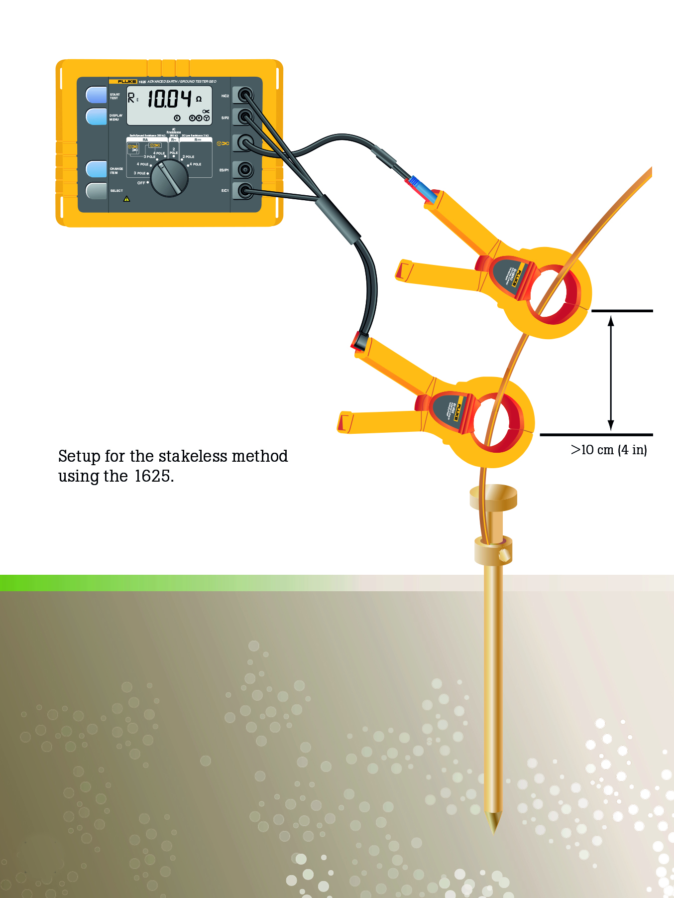
The Fluke 1625 earth ground tester can measure earth ground loop resistances for multi-grounded systems using only current clamps. This test technique eliminates the dangerous and time-consuming activity of disconnecting parallel grounds, as well as the process of finding suitable locations for auxiliary ground stakes. You can also perform earth ground tests in places you have not considered before: inside buildings, on power pylons, or anywhere you don’t have access to soil.
This test method places two clamps around the earth ground rod or the connecting cable, each connected to the tester. Earth ground stakes are not used at all. A known voltage is induced by one clamp, and the current is measured using the second clamp. The tester automatically determines the ground loop resistance at this ground rod. Suppose there is only one path to ground, like in many residential situations. In that case, the Stakeless method will not provide an acceptable value, and the Fall-of-Potential test method must be used.
The Fluke 1625 works on the principle that in parallel/multi-grounded systems, the net resistance of all ground paths will be extremely low compared to any single path (the one under test). So, the net resistance of all the parallel return path resistances is effectively zero. Stakeless measurement only measures individual ground rod resistances in parallel to earth grounding systems. If the ground system is not parallel to the earth, you will either have an open circuit or be measuring ground loop resistance.
Ground impedance measurements
When calculating possible short circuit currents in power plants and other high voltage/current situations, determining the complex grounding impedance is important since the impedance will be composed of inductive and capacitive elements. Because inductivity and resistivity are known in most cases, actual impedance can be determined using a complex computation.
Since impedance is frequency dependent, the Fluke 1625 uses a 55 Hz signal for this calculation to be as close to voltage operating frequency as possible. This ensures the measurement is close to the value at the true operating frequency. Using this feature of the Fluke 1625, accurate direct measurement of grounding impedance is possible.
Power utility technicians testing high-voltage transmission lines are interested in two things. The ground resistance in case of a lightning strike and the impedance of the entire system in case of a short circuit on a specific point in the line. In this case, a short circuit means an active wire breaks loose and touches the metal grid of a tower.
Two-pole ground resistance
In situations where the driving of ground stakes is neither practical nor possible, the Fluke 1623 and 1625 testers give you the ability to do two-pole ground resistance/ continuity measurements, as shown below.
To perform this test, the technician must have access to a good, known ground, such as an all-metal waterpipe. The water pipe should be extensive and metallic throughout without insulating couplings or flanges. Unlike many testers, the Fluke 1623 and 1625 perform the test with a relatively high current (short circuit current > 250 mA), ensuring stable results.